ETHERNET TRIGGER AND SERIAL TRIGGER/TABLE
The Ethernet Trigger and Serial Trigger are Logic objects that are employed to send control messages from a Soundweb device to third party devices such as projectors and video switchers.
The third party device must be able to respond to messages without acknowledgement. A Soundweb device is not able to process any messages transmitted by the third party device.
SERIAL TRIGGER/TABLE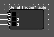
The Serial Trigger/Table is capable of sending messages at specified port speeds and settings. Messages are transmitted from the RS232 port located on the rear panel of the device.
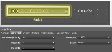
The RS232 port speed and settings are defined in the device’s Serial Port Properties. The device’s properties are displayed when the device in the Room is selected.
Left-click once to select the rack, then click a second time to select the device. The Acknowledge setting is not relevant to Serial Trigger/Table operation.
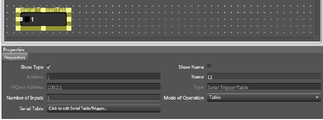
The Serial Trigger/Table settings are defined in the Properties which are displayed when the object is selected.
Number of Inputs can be adjusted from 1 to 12.
Mode of Operation can be set to Table or List.
The serial messages are entered in the Serial Table field by clicking the Click to edit Serial Table/Trigger button.
�
LIST MODE
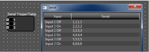
A message can be specified for each input state transition. A message will be sent when the input state changes from Off to On and when it changes from state On to Off.
e.g. A total of six possible messages can be sent from a Serial Trigger/Table object configured with three inputs as shown.
TABLE MODE
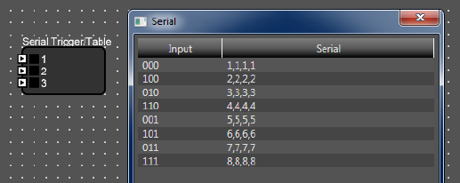
A message can be specified for each binary state transition of the inputs.
e.g. A total of eight possible messages can be sent from a Serial Trigger/Table object configured with three inputs as shown. 23 = 8
There is no limit on the number of Serial Trigger/Table objects added to the Logic Configuration. It is not necessary to configure all the required messages in a single object. If several objects are triggered simultaneously then messages will be queued before sending and none will be lost.
ETHERNET TRIGGER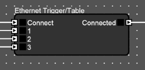
The Ethernet Trigger is capable of sending messages over TCP or UDP to a specified IP address and Port. It is not possible to start a Telnet session nor any other kind of terminal session. Messages are transmitted from the Ethernet Control RJ45 port on the rear panel of the device.
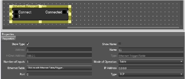 The Ethernet Trigger settings are defined in the Properties which are displayed when the object is selected.
The number of Inputs can be adjusted from 1 to 12.
The messages are entered in the Ethernet Table field by clicking the Click to edit Ethernet Table/Trigger button.
Mode of Operation can be set to Table or List. These function exactly like the Serial Trigger described above.
Messages are sent to the third party network device specified in the IP Address field. The IP port on which the third party network device should be listening is specified in the Port field. The Type field will determine whether the message is sent using the User Datagram Protocol (UDP) or the Transmission Control Protocol (TCP). Messages sent with UDP are not guaranteed nor re-transmitted. Messages sent with TCP are guaranteed and will be re-transmitted if the packets are lost.
UDP Type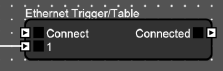
A message will be sent upon each input state transition. The Connect input and Connected output are not used.
TCP Type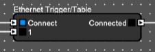
A TCP connection must be established before the inputs can be used to send a message. The Connect input is used to open and close a connection. The Connected output is used to indicate whether the connection is open or closed. The Ethernet Trigger will attempt to establish a connection when the Connect input is changed from Off to On. After a period of time the Connected output will change from Off to On once the connection has been established. The 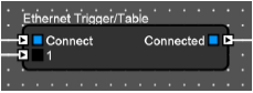 Connect input must be held On to maintain the connection. The Ethernet Trigger will close the connection when the Connect input is changed from On to Off. A message will be sent upon each input state transition while the Connected output is On.
There is no limit on the number of Ethernet Trigger objects added to the Logic Configuration. It is not necessary to configure all the required messages in a single object.
If several objects are triggered simultaneously then messages will be queued before sending and none will be lost.
�
Entering messages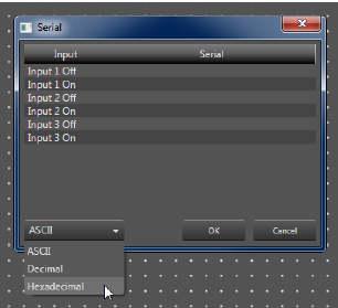
Messages are entered in the Properties by clicking on the “Click to edit...” button. This opens a window that displays a table showing the input states in the Input column and the messages in the Serial column.
Messages can be displayed and entered in Hexidecimal, ASCII or Decimal format. This can be changed using the drop-down box in the lower left corner. Double-click in the Serial.
When displaying messages in Hexidecimal format each byte must be separated with a comma. When displaying messages in Decimal format each byte must be separated with a comma.
When displaying messages in ASCII each character can be entered as required.
Line Feed, Carriage Return and other special characters cannot be entered while displaying messages in ASCII format. These must be entered while displaying messages in Hexidecimal format. The example below describes how to add a Carriage Return at the end of a message:
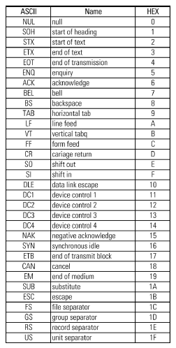
Enter the required message while displaying in ASCII format. 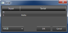
Change the display to Hexidecimal format. 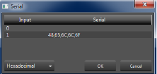
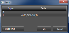
Add a D to the end of the message.
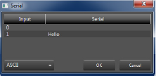
Carriage Return will not be visible when displaying in ASCII format.
�
