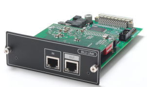
The BLU-SI option card provides BLU Link connectivity for Soundcraft Si Compact, Si Performer and Si Expression consoles. 32 channels can be transmitted onto the BLU Link bus and 32 channels can be received from the BLU Link bus. DIP switches allow the selection of consecutive channels in groups of 32. (The BLU Link card with the red DIP switches is mounted onto the carrier card with the black DIP switches.)
NOTE: Si1, Si2 and Si3 do not support the BLU-Si option card.
The BLU-Si is only supported in the following console software versions:
- Si Compact v3.0 or above
- Si Performer v1.5 or above
- Si Expression v1.5 or above.
Setting up the BLU-SI option card (single use)
WARNING: Before installing or removing the option card, make sure the mains power cord is unplugged.
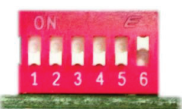
Adjust the red DIP switches to select the group of channels required using the table below. (On = Up) The transmit and receive channels should not be the same.
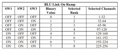
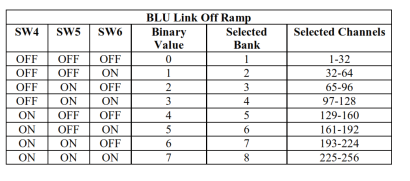
In the example below, the red DIP switches will set the card to transmit channels 1-32 onto the BLU Link bus and receive channels 33-64 from the BLU Link bus.
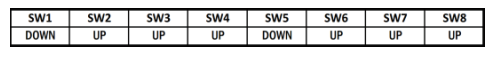
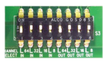
The black DIP switch must be left with its default settings as shown in the table below. No other settings are valid.
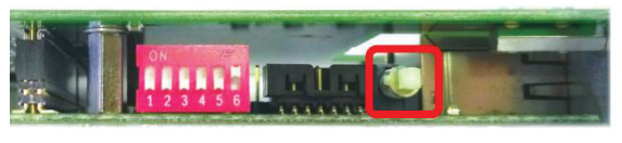
The Master/Child switch must be in the Master position which is pushed in. No other setting is valid. When set to the Master position the BLU-SI card will synchronise to the console’s word clock and will assume the role of BLU Link clock master.
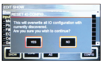
After installing the card into an available option slot the console’s I/O Configuration must be reset in order for BLU-SI option card channels to become available for patching. Press the MENU key and the select SHOW on the touch screen. Select RESET CONFIG and then select YES on the confirmation dialogue box.
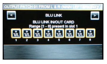
The BLU-SI card should now be successfully routed to the expansion bus inputs and outputs. The selected group of 32 transmit and 32 receive channels should now available for patching to the console’s channel inputs and from the bus outputs.
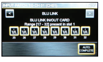
Note: When patching inputs and outputs on the console, the BLU-SI option card channels will always be displayed as 1 to 32 regardless of the actual BLU Link channels selected with the red DIP switches.
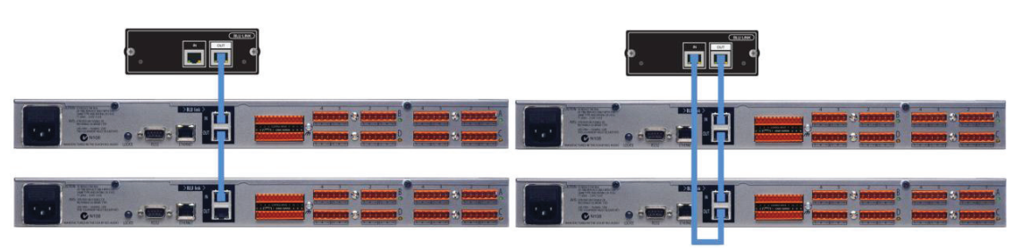
Connecting the BLU Link network
BLU Link devices can be connected in a daisy chain or a redundant ring. Each connection must use a straight cat-5e or higher cable no longer than 100m. Fiber converters such as the BSS Audio MC-1 will be required to extend the distance beyond 100m.
Setting up the Soundweb London device
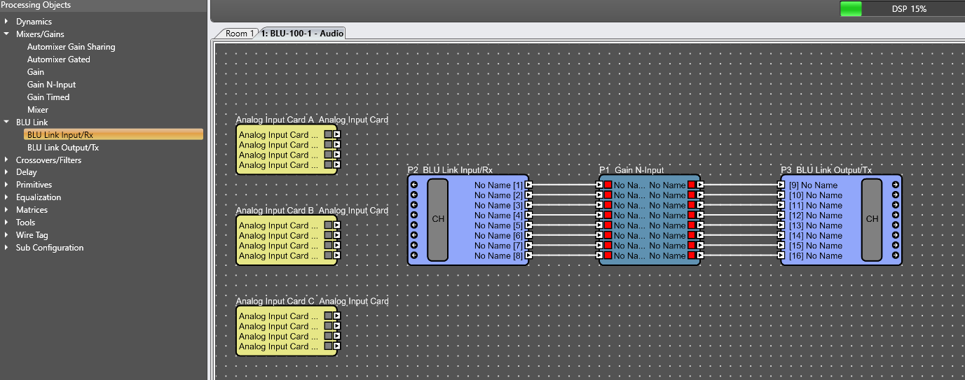
To send or receive BLU Link channels in a Soundweb London device a BLU Link Input or BLU Link Output object must be added to its Configuration and configured with the desired channels. Any number of these objects may be placed in the Configuration.
Receiving BLU Link channels
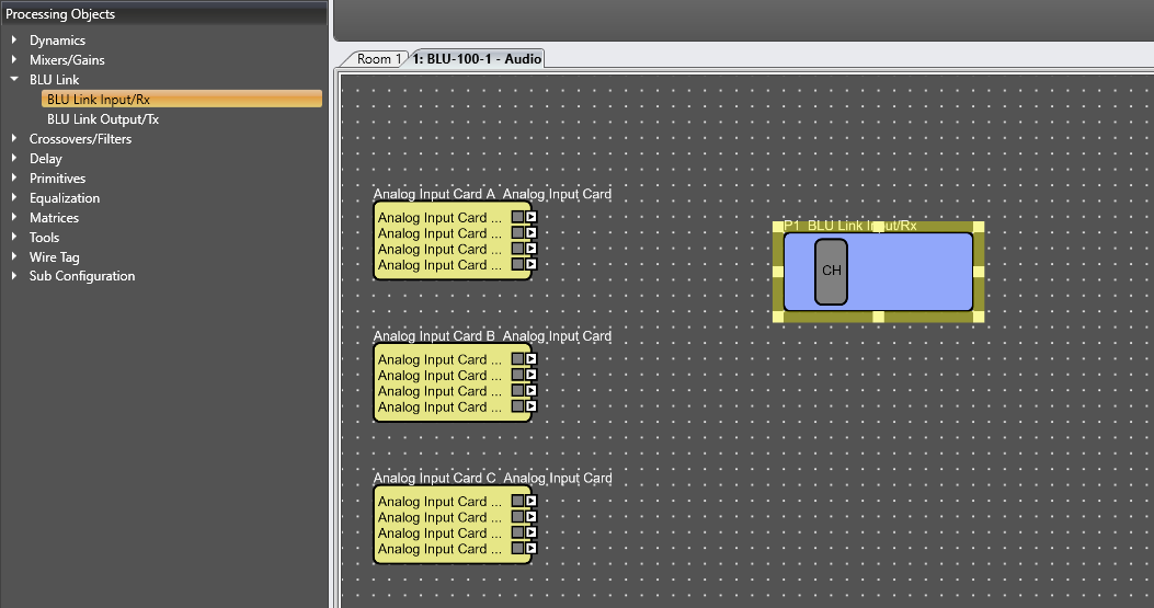
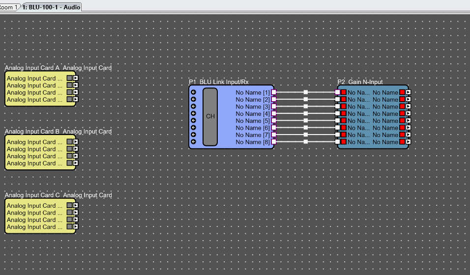
Double-click on the Soundweb London device in the Main window to open its Configuration. Right-click in the Configuration and choose BLU Link Input/Rx.
Drag in the BLU Link Input object and click on the CH icon in the object
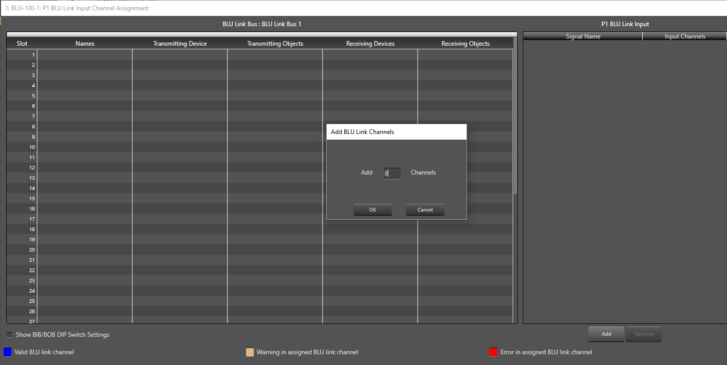
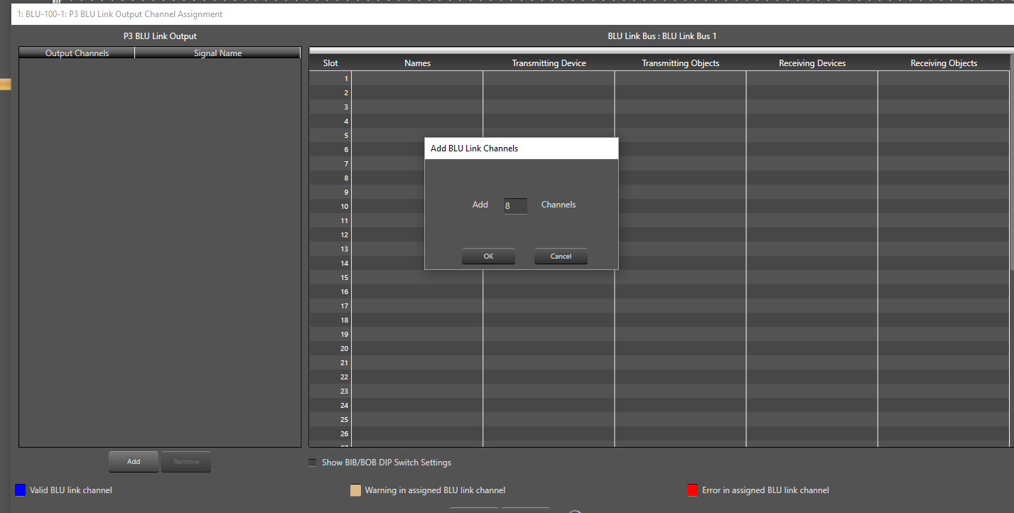
In the Channel Assignment window, first click Add and add the correct number of channels desired.
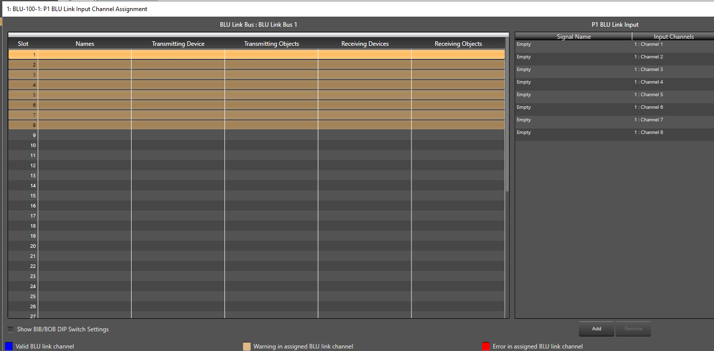
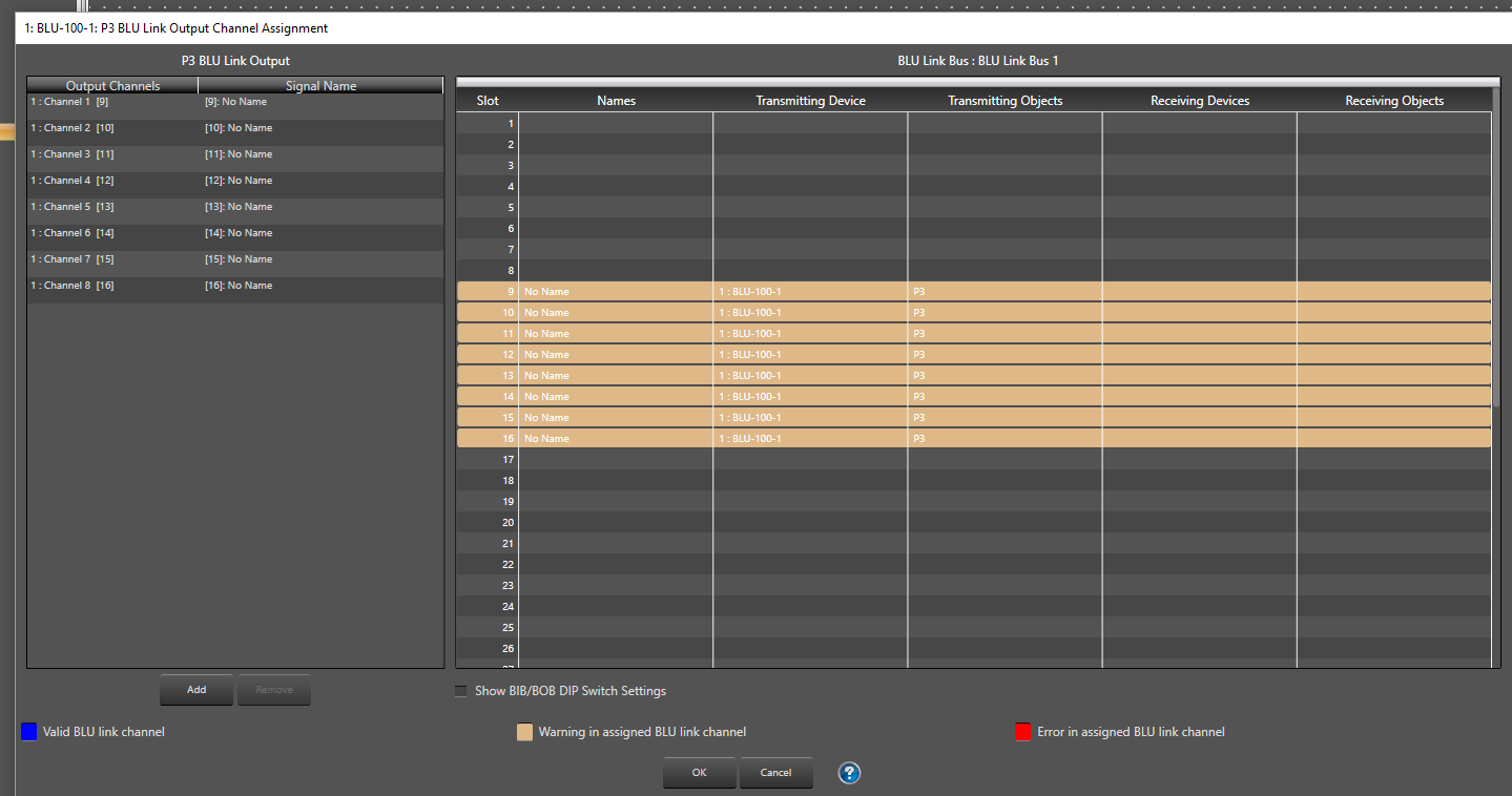
Select the desired BLU Link channels you want to assign in the list on the left-hand side (Use the SHIFT key to select multiple consecutive channels or use the CTRL key to select multiple non-adjacent channels)
Drag those channels over on top of the BLU Link input channels listed on right, then let go. The channels will then be associated.
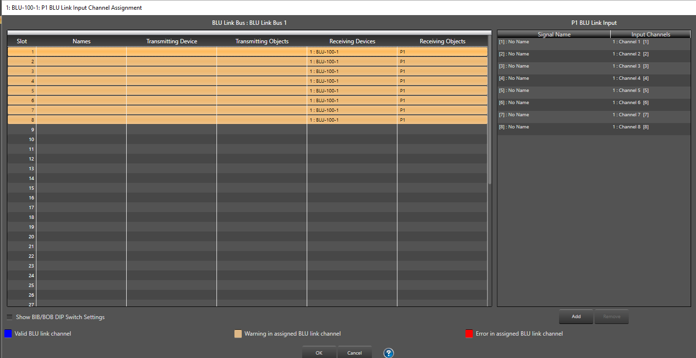
Click OK to accept and close the window. The BLU Link Input object is now configured and ready to be wired to other objects.
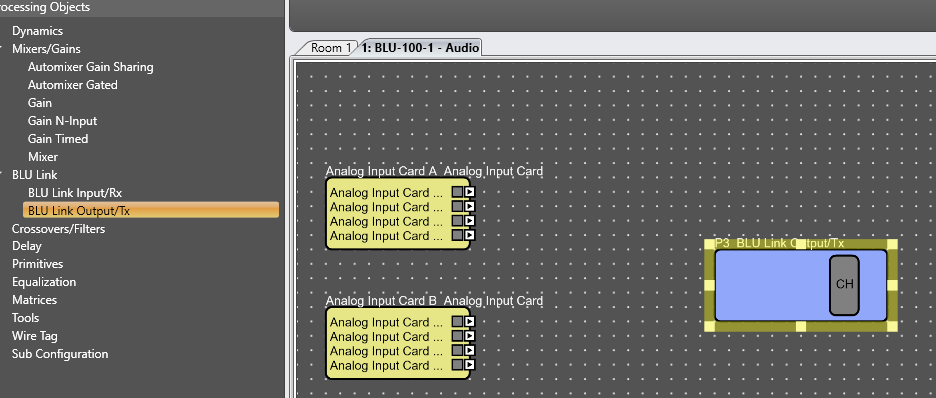
Transmitting BLU Link channels
Drag in the BLU Link Output object and click on the CH icon in the object
In the Channel Assignment window, first click Add and add the correct number of channels desired.
Select the BLU Link channels you want to assign in the list on the left-hand side (Use the SHIFT key to select multiple consecutive channels or use the CTRL key to select multiple non-adjacent channels). Then drag and drop on the BLU Link channesl you want for the transmitting device. Notice that you must use unique channel numbers.
Click OK to accept and close the window. The BLU Link Input object is now configured and ready to be wired to other objects.
Setting up the BLU-SI option card (multiple use)
Special clocking considerations must be taken into account when two or more consoles with BLU-SI cards are used on the same BLU Link network. Each BLU-SI card synchronises to the console’s internal word clock therefore all consoles must be synchronised together so that the BLU-SI cards are all synchronised.
There are two ways to synchronise multiple consoles together:
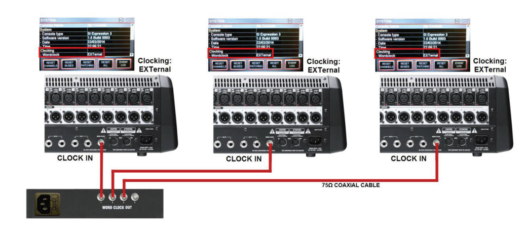
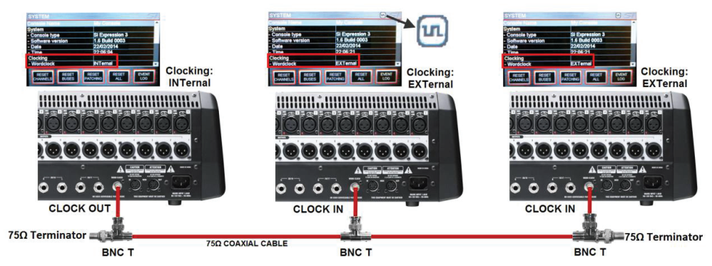
- Delegate one console that provides word clock to the other consoles. Set the BLU-SI option cards as instructed above. The console providing the word clock must derive its word clock internally.Press the MENU key and select SYSTEM on the touch screen.
Set the Wordclock setting to INTernal. The console’s internally generated word clock will now be present on the WORDCLOCK BNC connector. The consoles receiving the word clock must derive their word clock from an external source. These must have the Wordclock set to EXTernal. The WORDCLOCK BNC connector will be ready to receive external word clock.
- If there is no valid word clock then the Clock icon with an exclamation mark is displayed and the console will run from internal clock.

Use an external generator to distribute word clock to each console. Set BLU-SI option card as instructed above. All consoles will be deriving their word clock from an external source. These must have the Wordclock set to EXTerna.