Working with GPIO control

GPIO (General Purpose Input Output) – also known as control ports or even sometimes called logic controls since they report logic levels.

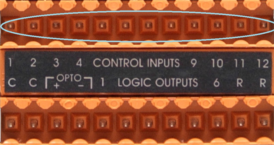
There are 12 inputs and 6 outputs on the control port terminal block in the center of the back panel on BSS units (the one exception is the BLU-GPX which has considerably more).
12 Input connections

6 Outputs
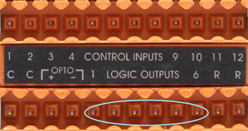
These ports can be set up in 2 or 3-wire mode which we will cover shortly. By default the configuration is 2-wire mode meaning that inputs or outputs are connected between the appropriate pin specified in the design and one of the two common connections at the bottom on the left.

There are other connections on this terminal block, but we will cover those later.
Project 1 - Indicate the status of a Mute with an LED in the real world
The 6 outputs can each supply 5 volts at 10 milliamps(mA) which is enough to light a simple LED.
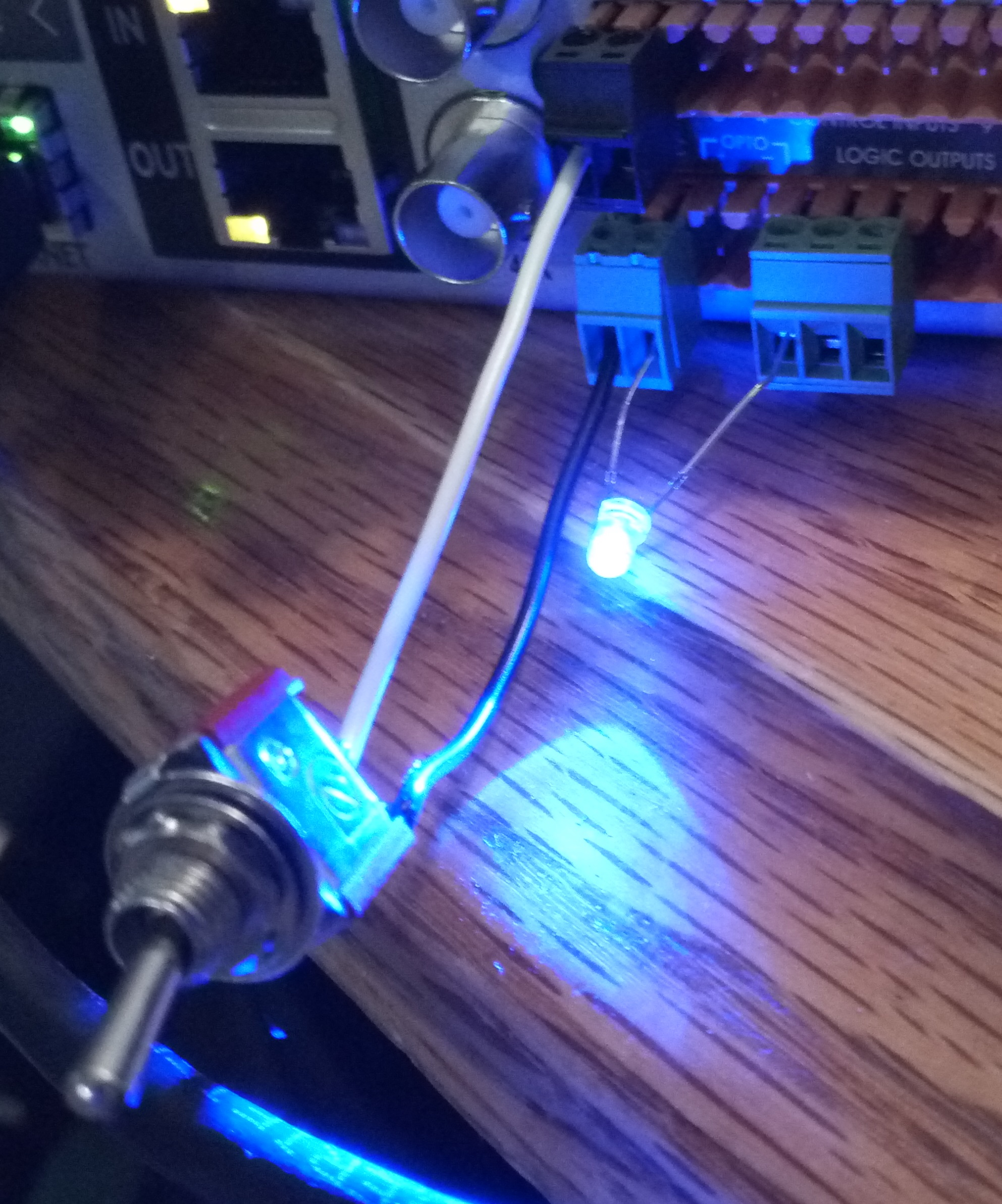

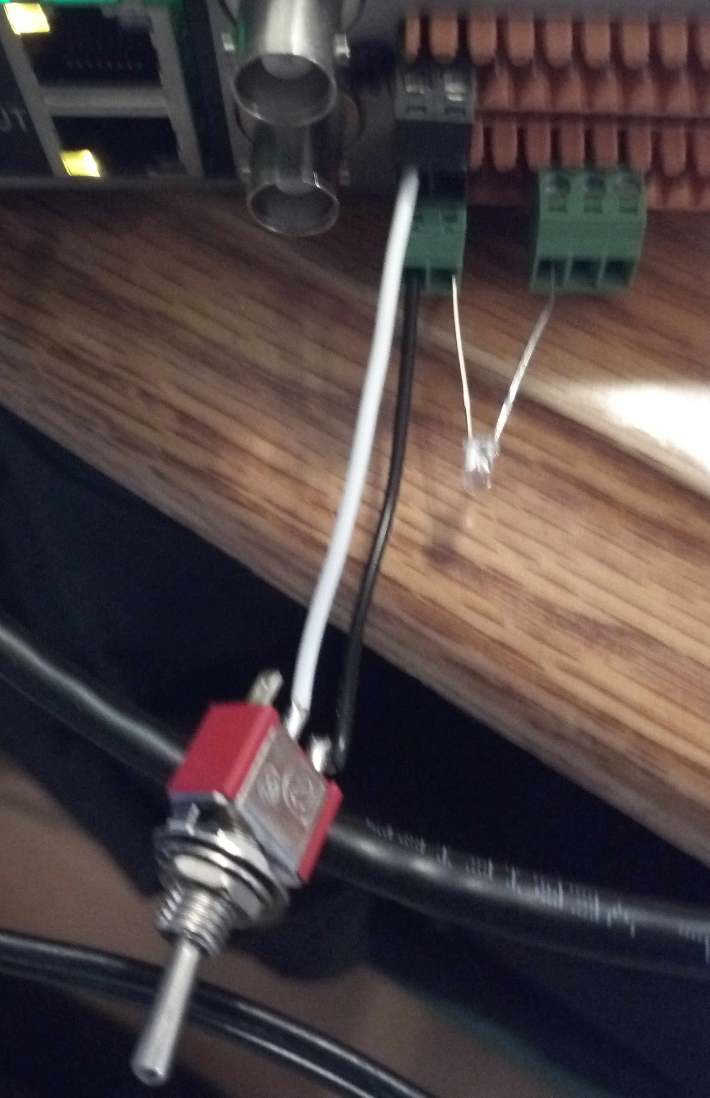
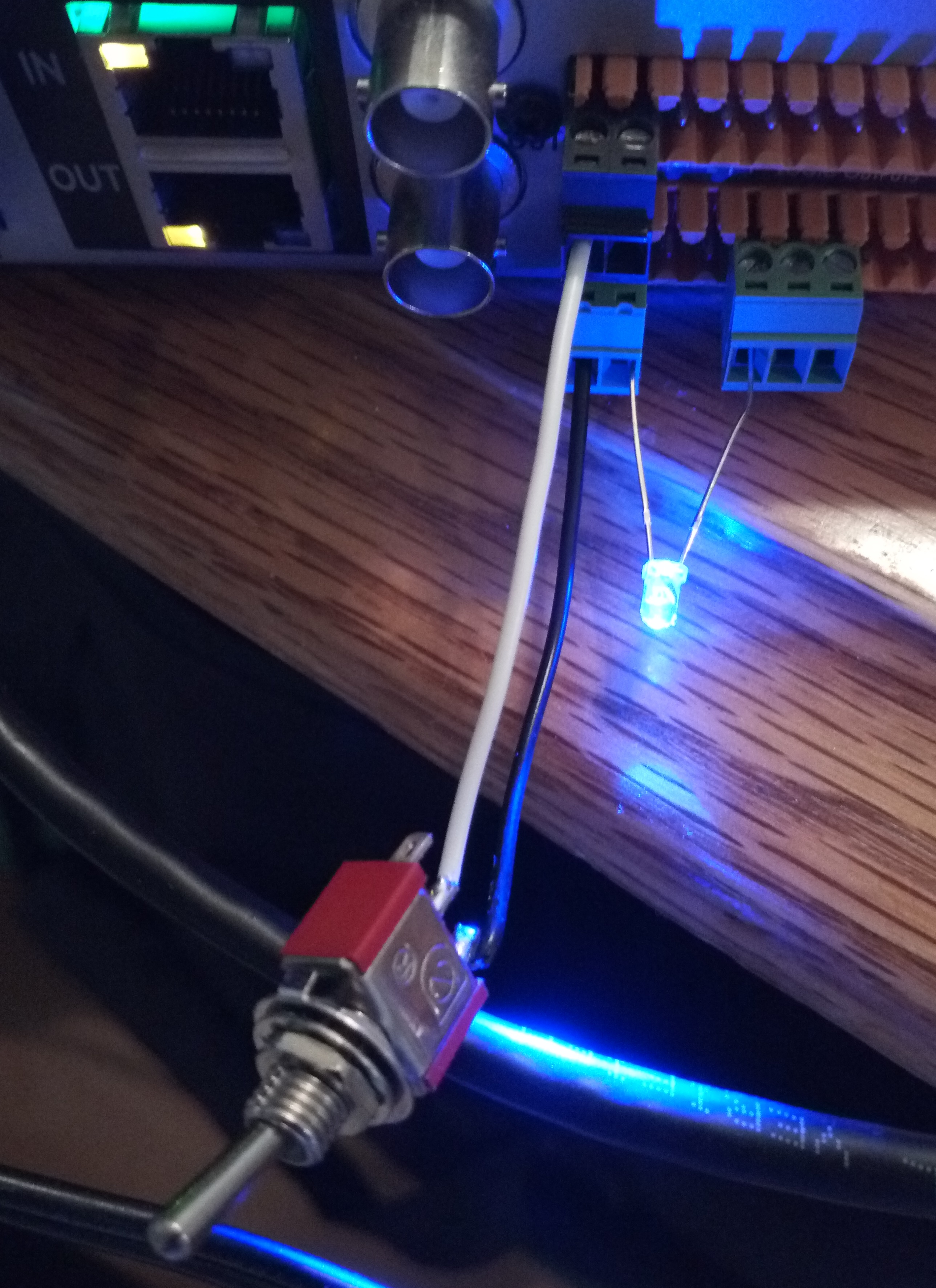
In the picture above you see a double pole single throw [DPST] switch connected to Control Input 1, and an LED connected to Control Output 1. The LED is polarized, meaning it will only light if the correct voltage is applied in the correct direction.
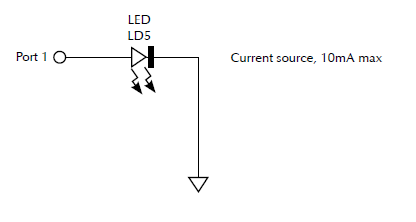

The port pin supplies the positive voltage and the triangle symbol refers to common ground or one of the two ground connections(either can be used).
The LED comes with one leg longer than the other. The longer leg is the “Anode" and is where the positive(+) voltage is applied. Connect the longer leg to control port output 1 and the shorter leg to the second common ground connector. The switch is connected so that when it is closed it connects the control port Input 1 to the common ground.
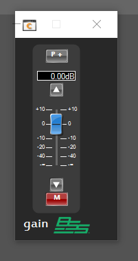
In Audio Architect add a DSP to the Venue and add a mono gain to the DSP configuration that can be used to mute the signal.

Double-click on the mono gain to open its default control panel.
At the top of Audio Architect, select the Soundweb London tab and choose “configure control ports" in the ribbon.
Control-click-and drag the mute button to BOTH control port INPUT 1 and control port OUTPUT 1.
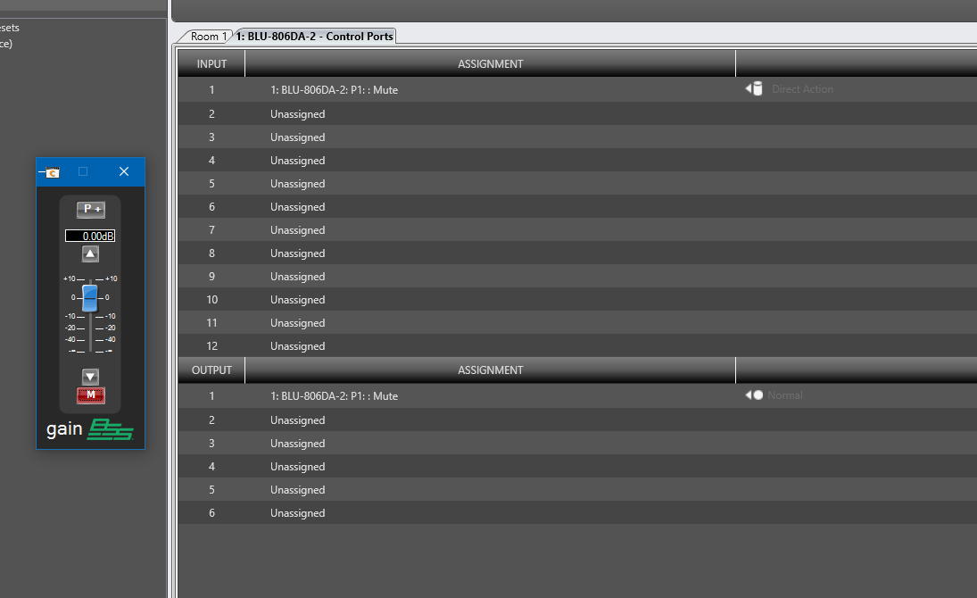
The input will read the state of the switch connected to input 1 and output 1 will change the state of the LED.
Go online and load the design into the device. Because the mute was off when going online and the switch was open, the mute and the LED stayed off.
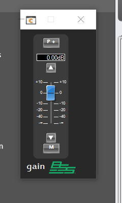
If the switch is changed to the closed state, the mute and LED will turn on.

Project 1 – alternative
Maybe the user wants to have the LED off when the mute is on(no sound) and the LED lit when audio is passing. We can use logic to reverse the output state of the LED.
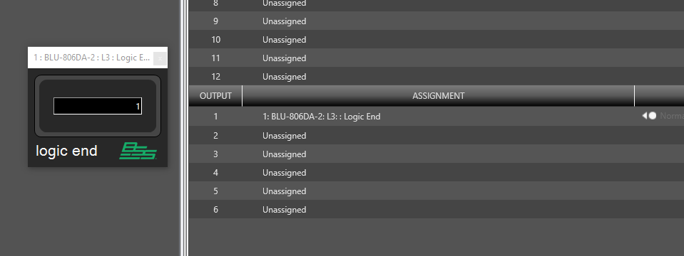
Go to the Configure Logic window. Add a logic Source, a logic NOT gate and a logic End and wire them together as shown. The NOT gate outputs the opposite of what comes in.

Use an exact link to link the mute to the logic source. Replace the mute on the control output assignment with the new logic End.
Go online again and load the changed design into the device.

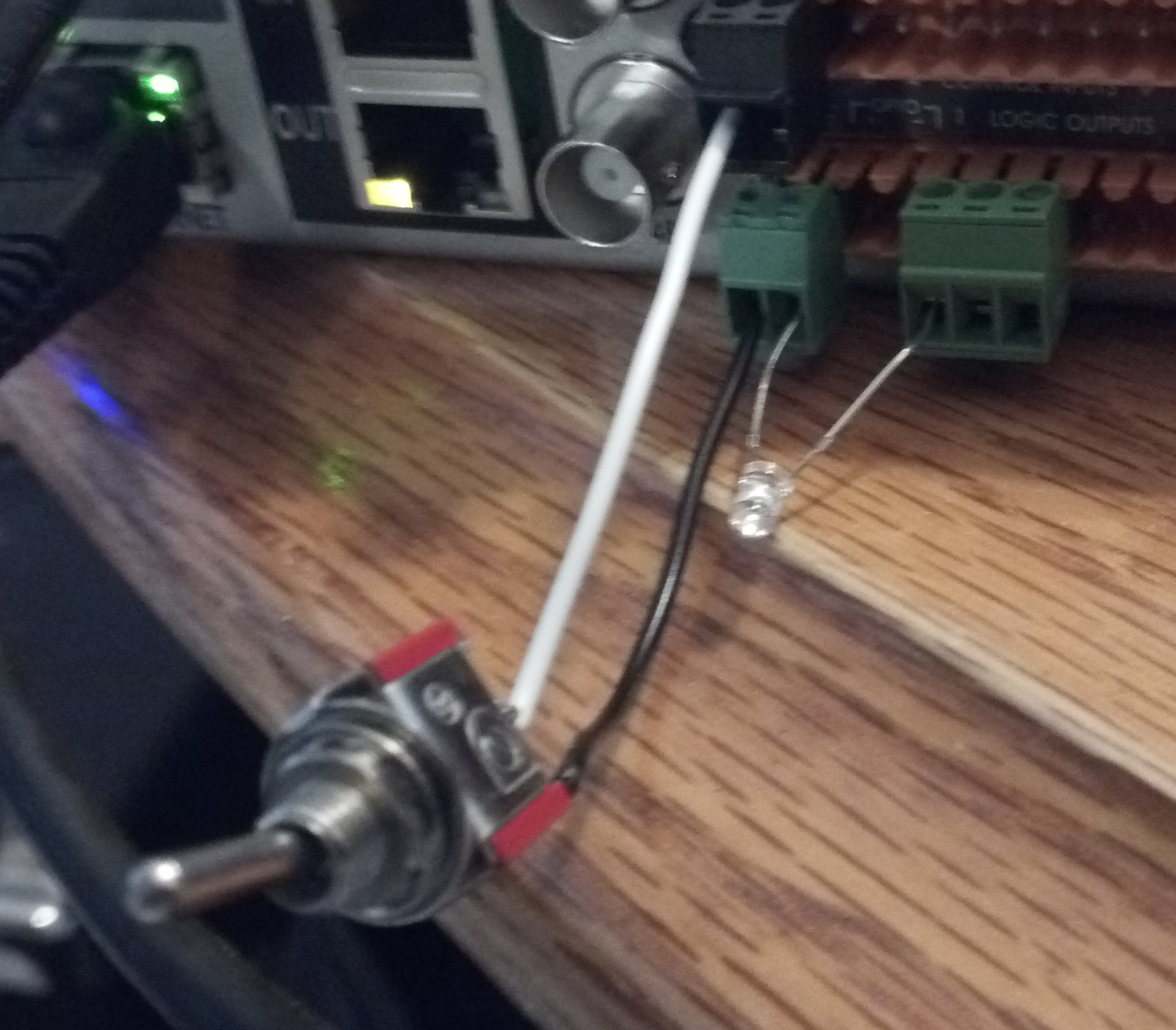
When going online the mute is off (unmuted) and the switch is in the open condition so the led is On.


Closing the switch mutes the audio and turns off the LED.


Wire Modes
Wire modes describes the number of control wires between the potentiometer and the DSP. This also affects the type of potentiometer that can be used.
Two Wire Mode
In Two Wire Mode the connections to the controller only require a connection to the input port and a connection to common ground.
Different types of controls can be connected to the control inputs. We have already illistrated that an external switch can trigger a state change on a mute. But as seen in the drawing here, potentiometers(variable resistors) can also be used to control volumes and resistor ladders can be used to make selections.
Three Wire Mode
The main difference between two wire mode and three wire mode is the third wire which is connected to one of the two R connections and refers to a “reference voltage." In two wire mode there is a reference voltage but it is supplied internally. In three wire mode the reference voltage is supplied by the wiring. The reference voltage allows some devices more versatility on how they control the design objects.
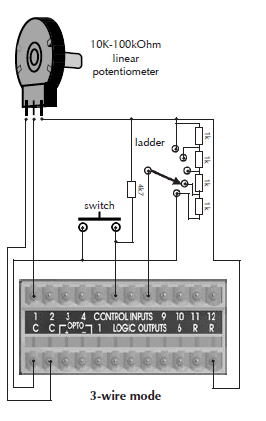
Note: you cannot mix 2-wire and 3-wire controls. They must all be of the same type.
Project 2: Fire Mute
Muting audio based on the state of a fire alarm relay. The fire alarm relay connects between one of the 12 Control Inputs port and one of the two common ground connections.
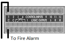

Fire alarm connections can be configured in one of two methods Normally Open(NO) and Normally Closed(NC)
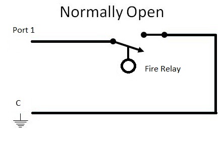
Normally Open(NO)
In a NO circuit there is no completion of the circuit until the fire alarm relay closes.

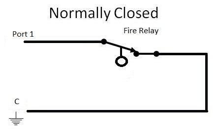
Normally Closed(NC)
In a NC circuit there is constant completion of the circuit until the relay opens which effectively breaks the circuit. This is more common and the advantage to this is that should wiring get damaged you might get a false alarm but you can be confident that as long as wiring is not damaged you know the fire alarm will trigger when the alarm relay opens. This is also called a self monitoring circuit.


In audio architect add a Gain-N object and pass all the outputs through that object.
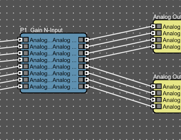
Double click on the Gain-N block to open the control panel. This object has a Master mute that will mute all the signals.
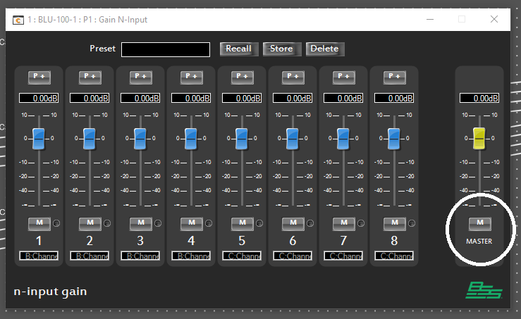
Click on “Configure Control Ports" in the ribbon to open the Control Port window. Control click and drag this mater mute to the control port you wired your fire mute too.
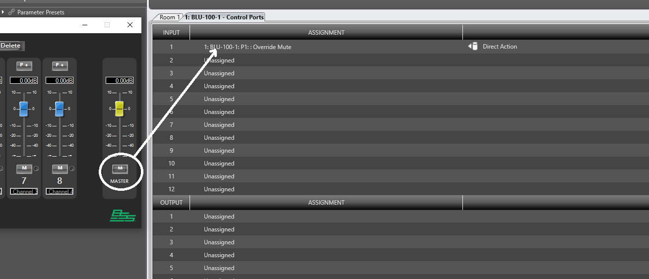
The mode is important here… if you have a “Normally open" fire relay then the default of “direct action" will be appropriate because it will turn on the mute when the circuit closes.

If the circuit is “Normally closed" then you will want to select “Direct Action 'inverted'" so that the mute triggers when the Circuit “Opens."
Project 3: Dry Contact Closure
Without external hardware a true “Dry" contact closure is not possible without external hardware(some sort of relay).
A relay is made up of two parts. A coil that when charged will cause a switch to either closed or open depending on the design.


Some relays can operate off of the 5 volts and 10mA or less that is provided from a control port output.
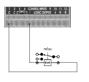

Other relays will work off the 5 volts but require more than 10mA. An additional roughly 10mA can be obtained by adding multiple control ports wired together. In the example below this could drive a relay with up to 40mA of current required (All ports need to be toggled to the same state when a change in state is made).
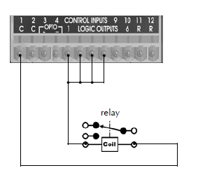

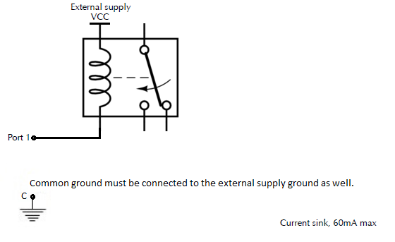
If your relay is NOT a 5 volt relay you can also connect a higher voltage relay using the logic output and an external power supply of the appropriate voltage. Control port outputs can sink up to 50V DC up to 60mA using the “current sink" wiring illistrated below:

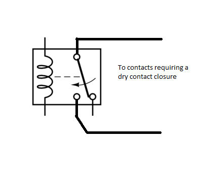
Whichever method you use to trigger the relay, the following connection would be made to your device requiring the contact closure:

One final caveat for contact closures. In SOME cases with some devices, a true DRY contact closure is not required… This will vary from device to device but if it is somewhat fault tolerant and can deal with a higher resistance the relay can be dispensed with and a wiring using an external connection like this may work.
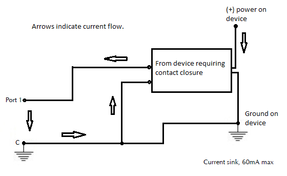

Note: this is still subject to the 50 volts and 60mA maximum requirements of a control port output. If a device expects more current to flow or cannot deal with a higher resistance in-between the terminals of the contact closure then a relay is required to get the current to flow!

Project 3 - Alternate
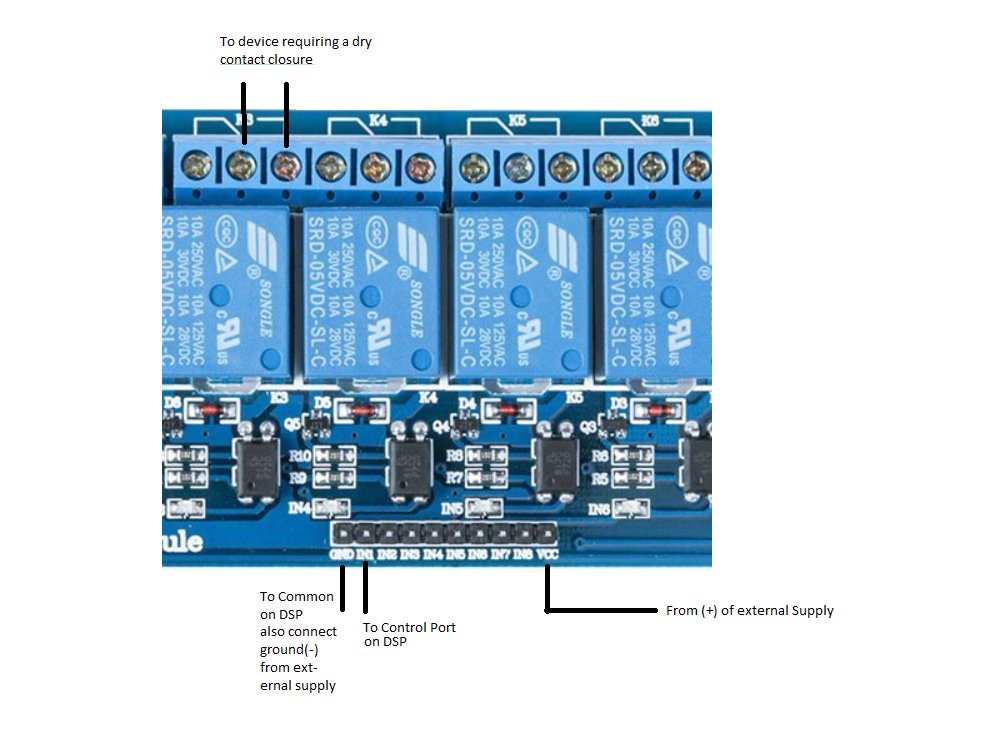
Use of a relay board that recognizes logic levels. The biggest advantage here is that many of these board are optically isolated and not limited to 60mA of current draw since the have their own circuitry and power supply.
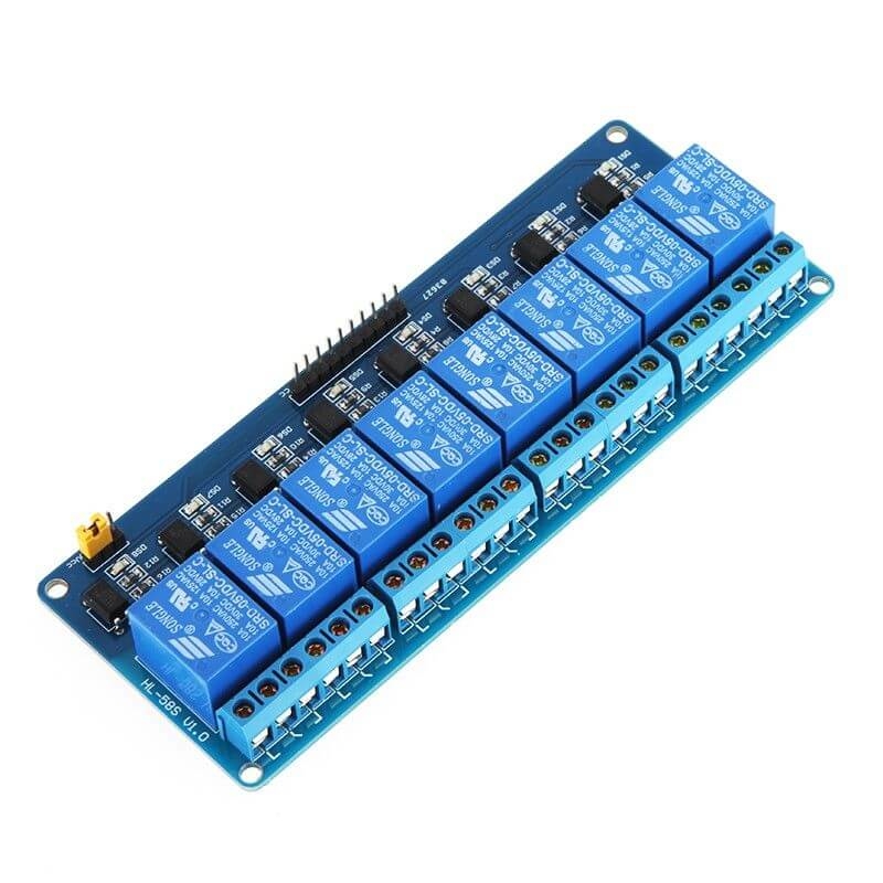
These boards come in single relay as well as 2x, 4x, 8x and 16x from various manufacturers and with various tolerances. They recognize the logic “1" and “0" states. They are pretty common if you go to your preferred online retailer and search for “relay board" you will find many offerings. Each of these will be a little different but in general they all require external power and that their grounds be tied to the common ground on the DSP. Typically the size of the relay depends on what you want it to control and how much voltage needs to be controlled.
Generally the BSS DSP is wired to the control board as is indicated below:
