INTRODUCTION
ROOM GROUPS
ROOM PARTITIONS
HOW TO CREATE A ROOM COMBINE OBJECT IN AUDIO ARCHITECT
STEP 1: CREATE THE ROOM LAYOUT IN YOUR DESIGN.
STEP 2. DEFINE WHAT ROOMS CAN BE COMBINED.
STEP 3. ADD AN Y PARTITIONS
STEP 4. ADD THE ROOM COMBINE OBJECT TO YOUR SIGNAL FLOW.
THE ROOM COMBINE OBJECT
SOURCE INPUTS
BGM
DEFAULT CONTROL PANEL
OPTIONS
USE AUTOMIXER
MIXING/SEPARATE BGM PATH
USE SIGNAL NAMES
ENABLE STEREO FUNCTIONALITY
PRIORITY PARTITION MODE
ATTACHED TO VENUE CONTROLS
CONTROL OPTIONS
PARTITIONS
PRESETS
THIRD PARTY CONTROL
CUSTOM CONTROL PANELS IN AUDIO ARCHITECT
USING THE VENUE WINDOW FOR CONTROL.
ADVANCED TOPICS
WIRELESS MICROPHONES
ROOM COMBINE IN CONFERENCING
LINKING PARTITIONS
LINKING GROUPS
Today, many hospitality and conferencing facilities rely on flexible room configurations to better suit customer needs. This can be anything from Ballrooms that are divided into smaller rooms to conference rooms that can be expanded to other conferencing rooms. For the spaces to function in a flexible manner, the room control and audio sources must be able to be dynamically shared across areas. Typically, this includes sharing the inputs of both areas thus combining any mixers between areas. This can also be used as a method for overflow where additional sources are not mixed but the audio is routed to other areas. Any Background Music or BGM is typically linked between areas as well to give continuity between the spaces. Room groups and partitions can be controlled through many means including Audio Architect custom panels and venue window, third party control systems, device control ports and Ethernet controllers.
Room grouping is a way of combining rooms based on a numerical value. If two or more rooms have the same group value they are combined. The number of possible groups can be determined by dividing the total number of rooms by 2 rounded down. Thus, if there are two rooms there is only one group available which is 1. With four rooms the number of groups would be 2. With 7 rooms the number of groups would be three and so on.
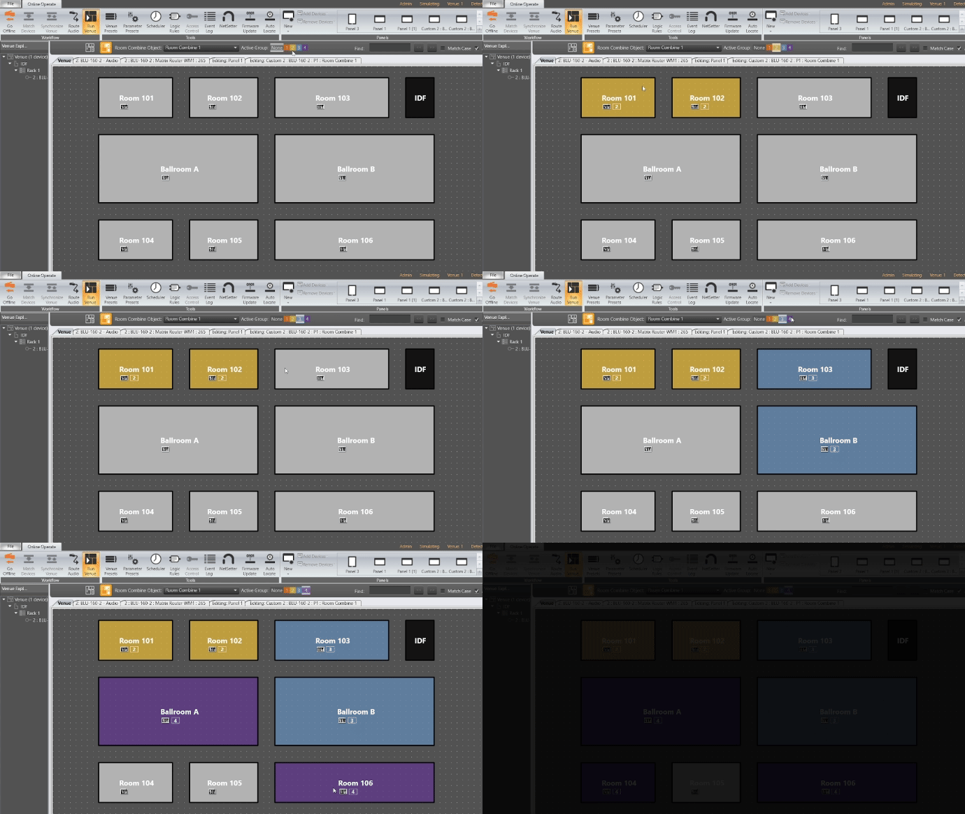
In the image below there are 8 rooms that can be combined, thus 4 groups. Rooms 101,102,104 and Ball Room A are currently in Group 1 and share audio. Rooms 103, 106 and Ballroom are currently in group 3 and share audio. Room 105 is in group 2 by itself and doesn’t share any audio.
We also allow the value of a group to be zero, which is a simple way to designate that a room is not part of a group. Thus, if a room is assigned a group value zero it is in an uncombined state even if other rooms are also group 0.
ROOM PARTITIONS
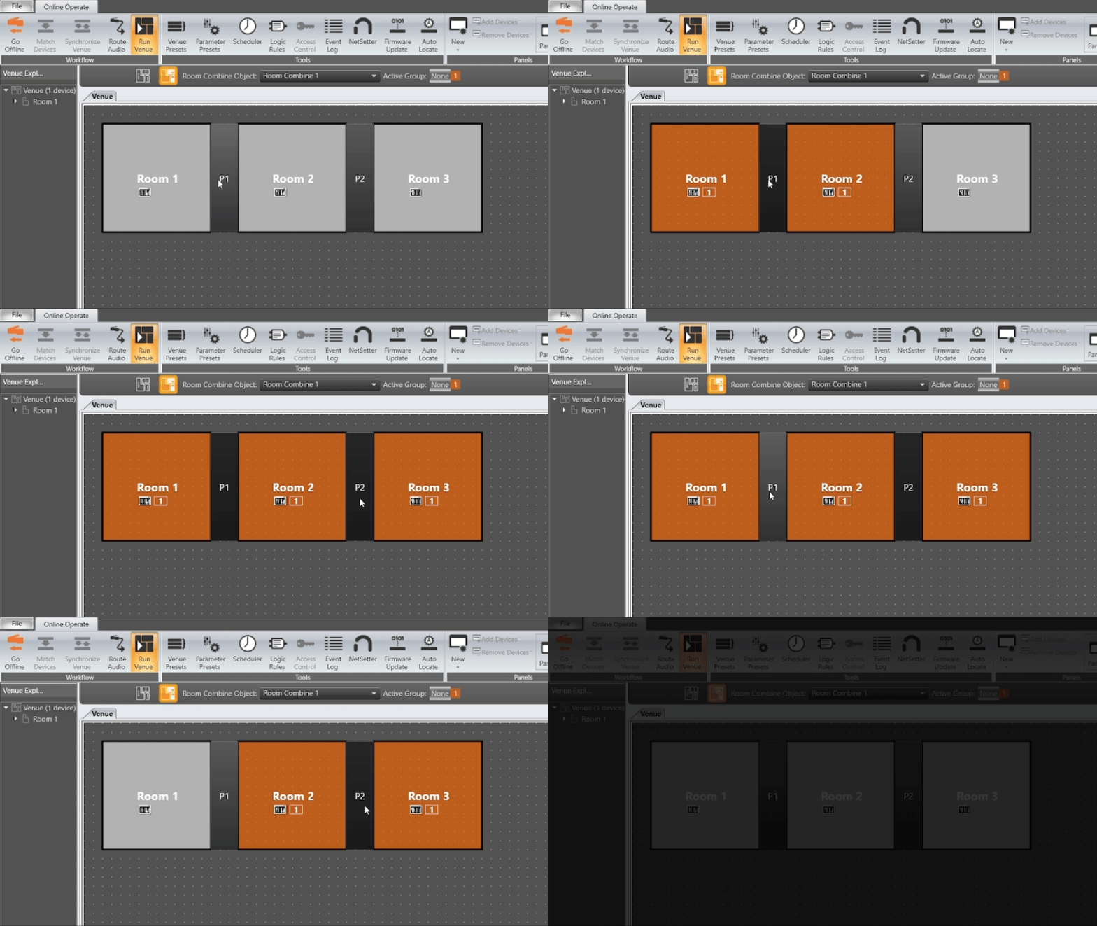
As an alternative to room groups there is another method using partitions. Partitions are basically switches that combine and divide rooms. If a partition switch is open (on) both rooms are set combined and their group number is set the same. This allows the user to use a simple control like a contact closure on an air wall or button on a control panel to combine two rooms. If this all seems complicated, don’t worry the Room Combine object handles this logic and functions and simplifies the design.
HOW TO CREATE A ROOM COMBINE OBJECT IN AUDIO ARCHITECT
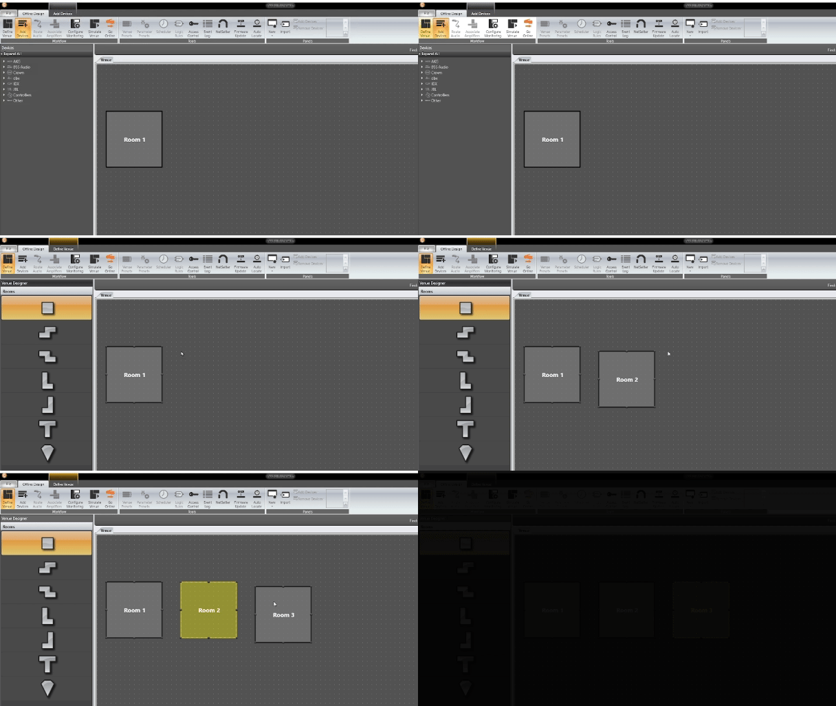
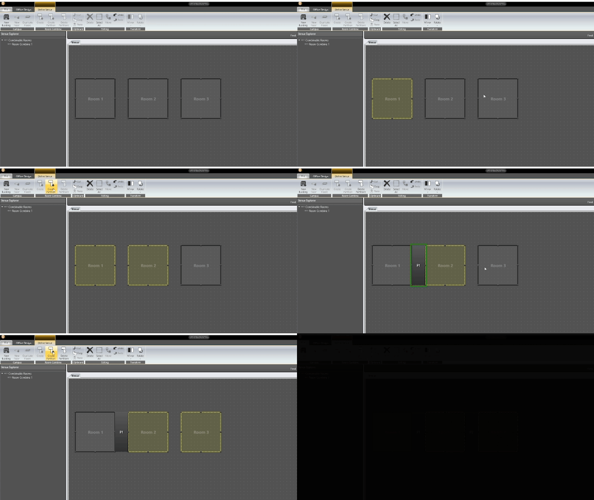
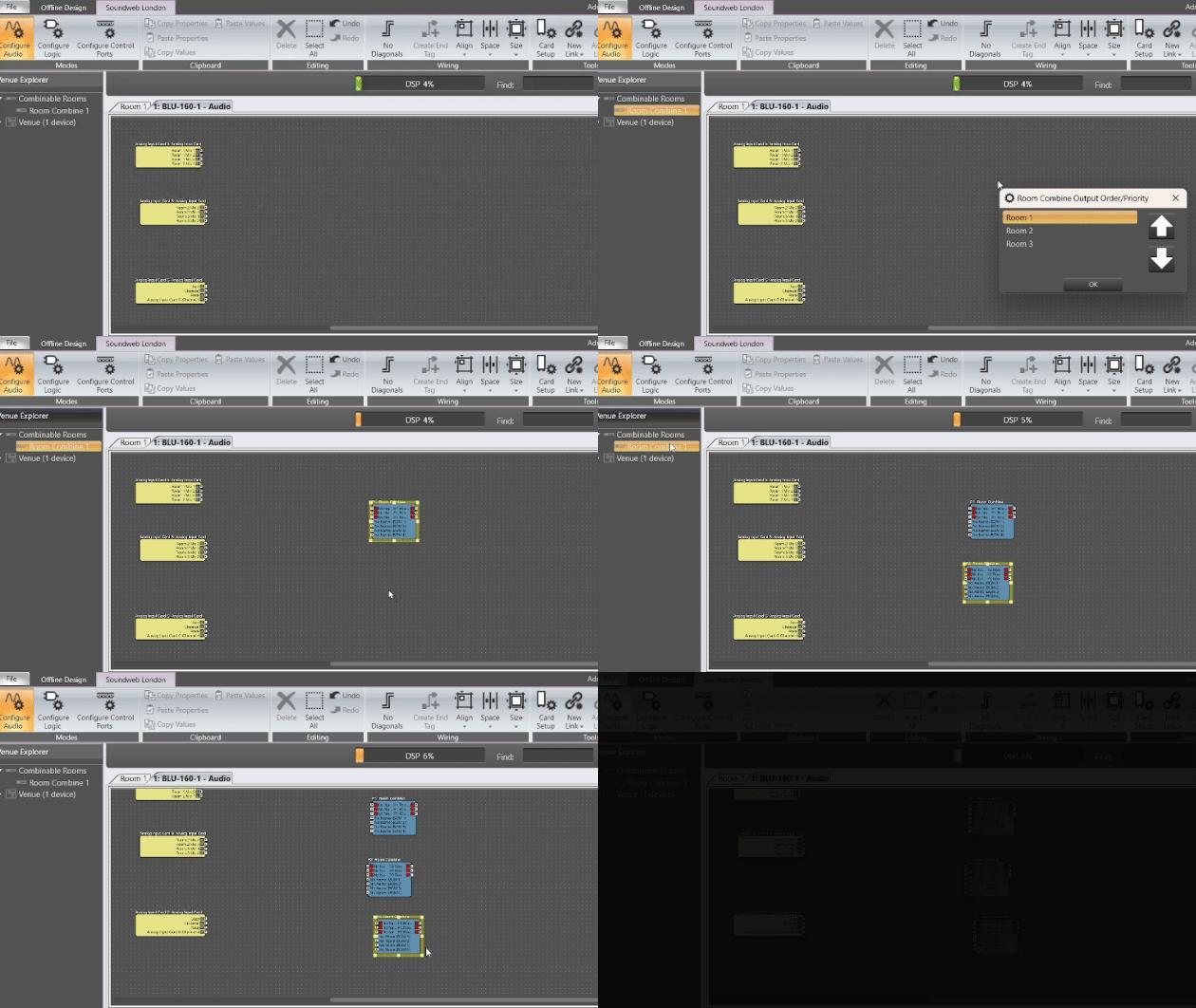
This is done under define venue. Here you can add rooms to the design file by dragging rooms into the venue window. For our first example we will use three rooms.
.
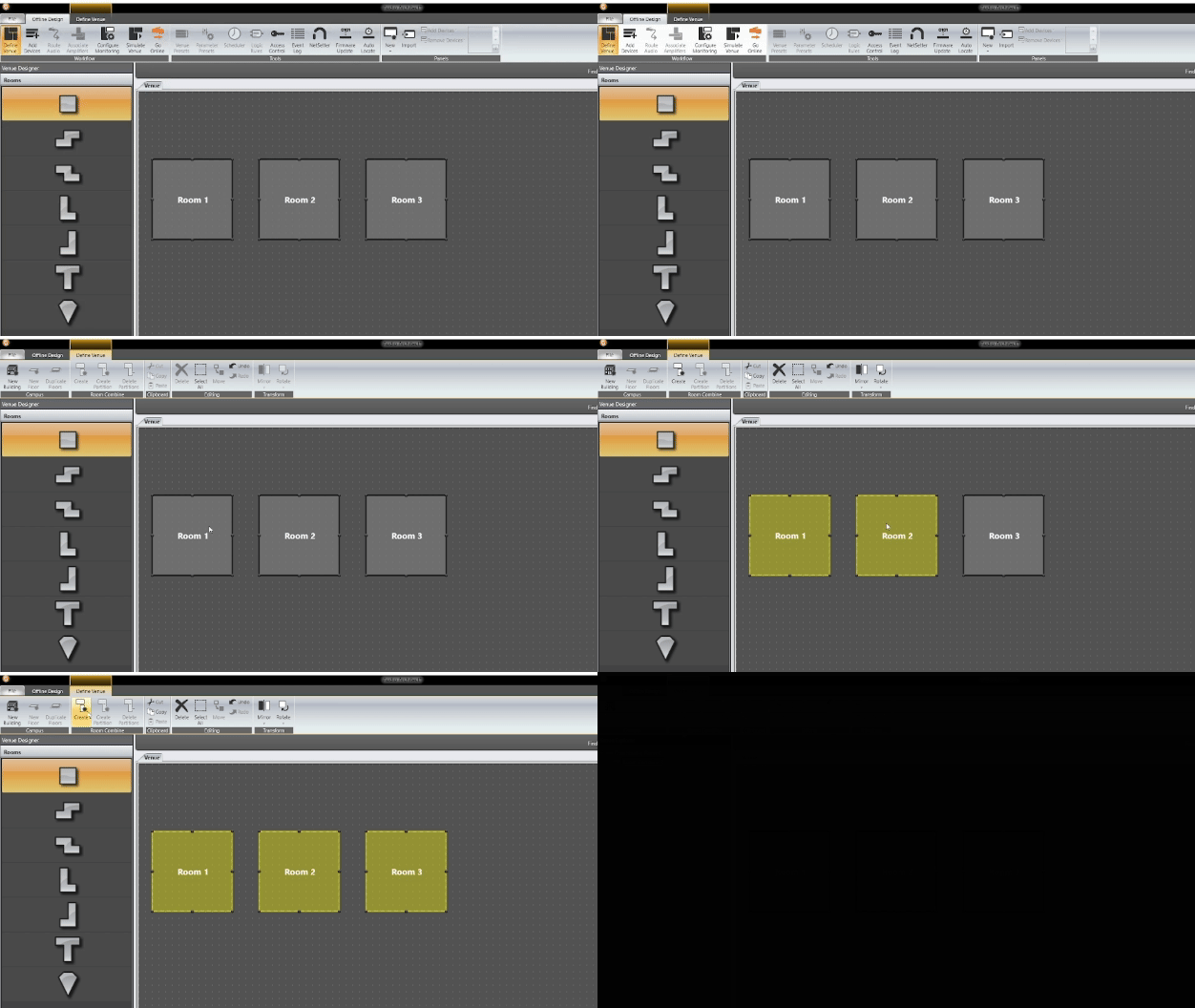
- Click on the Define Venue tab at the top.
- Next select the rooms you want to be included in the Room Combine Object. This can be done by Shift+Clicking or Ctrl+Clicking the rooms to add or remove them.
- Then click on create.
Partitions can now be added to the room combine by selecting two rooms and clicking Create Partition. Since we have three rooms, we will add a second partition between rooms two and three.
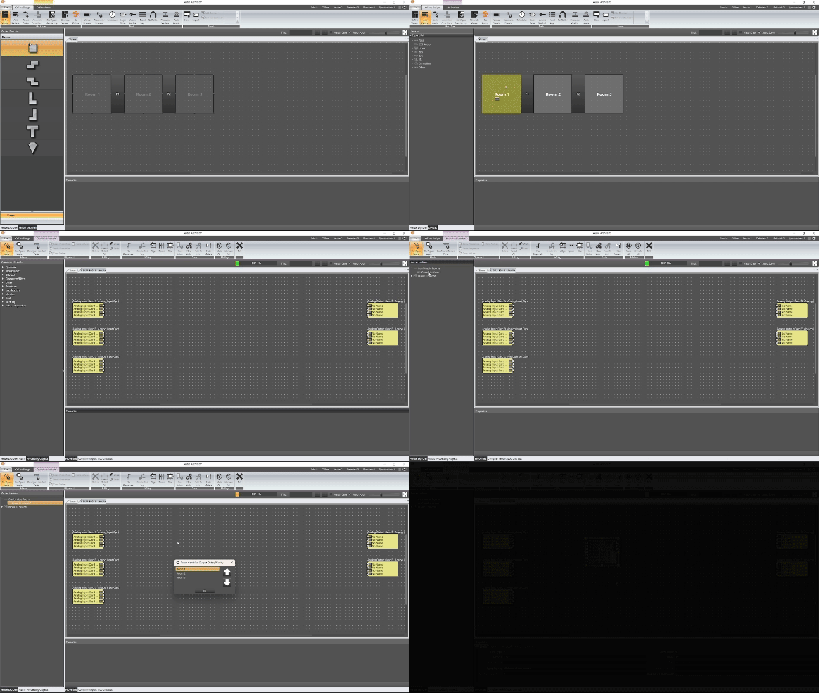
- Go back to add devices mode.
- Open the DSP where you want to have the room combine object. The room combine object will show up under Venue Explorer. Simply drag it into your configuration.
- You will be prompted with a dialog box that will allow you to change the order of the rooms. Typically, no change is re-quired unless you decide to use priority partition mode. In this case the order would determine the room priority for sources and volume when combined. More on that later.
- Once you select ok you will be presented with a room combine object.
The first three inputs are for Room source. These will typically be tied to a Mixer or Gain Sharing Automixer for each room. When the rooms are combined, the output of the rooms automixers are summed together and therefore audio is shared between the room outputs. When the rooms are separated, each room source only feeds that rooms’ output or room mix.
.gif)
The Room Combiner object also has BGM (Background Music) inputs. These inputs can be used for any kind source selection that needs to happen such as switching music sources or selecting different devices for media playback etc. The number of BGM sources can be scaled up or down in the object properties.
.gif)
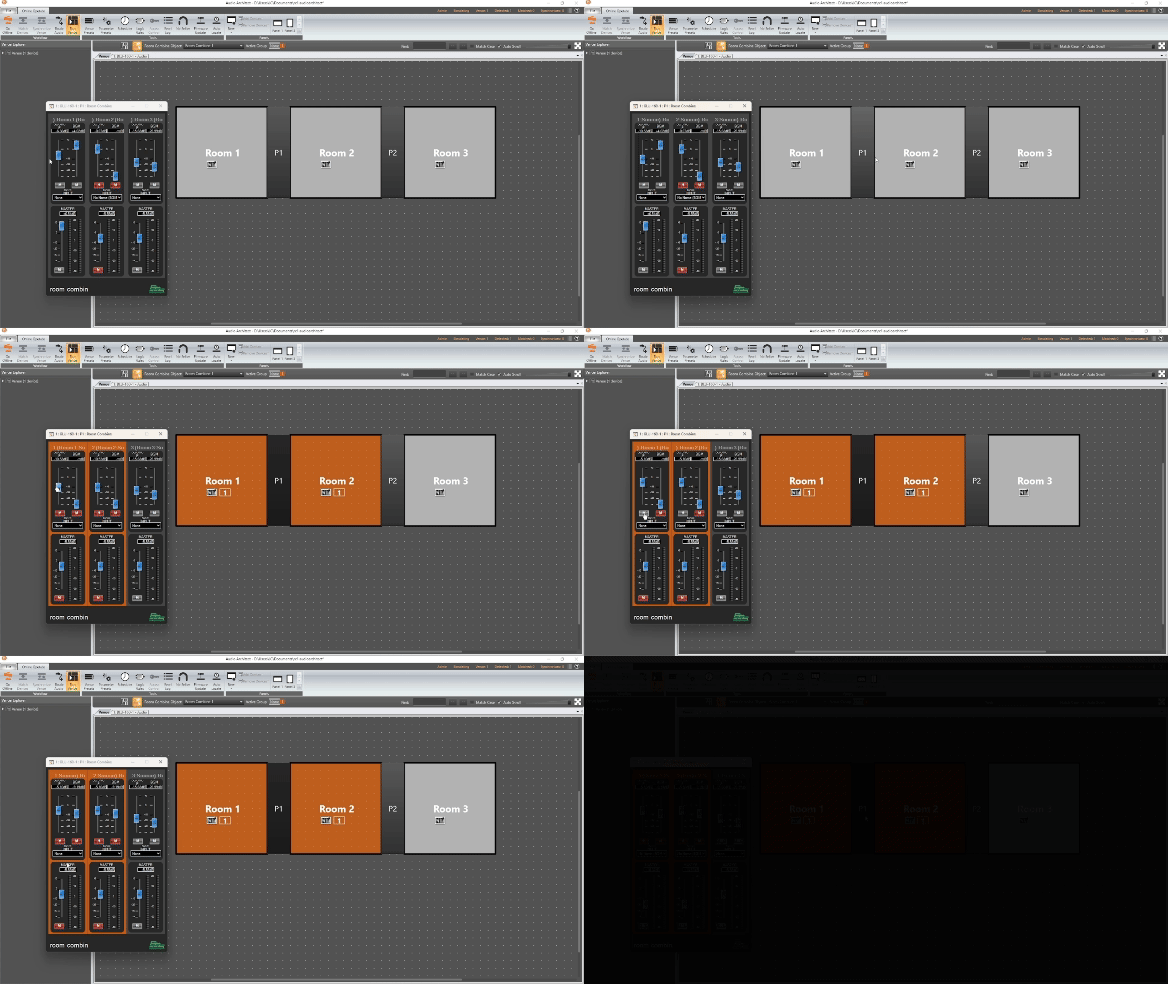
The default control panel for the room combine object will also show that the faders mutes and BGM sources are linked when room are combined and unlinked when the room are uncombined. Also of note, two room will always take the lower of two values between the rooms when combined. i.e if one fader is at 0dB and another at -20dB they will both go to -20dB. This applies to mutes and BGM inputs as well. The only exception is if priority partition mode is enabled. In this case rooms will use the room order to determine which settings they take when combined.

When combine mixers in difference spaces we can increase the number of open microphones which can affect the system gain if enough microphones are opened up. Use Automixer is a way of combining the Auto mixer side chains so the act as one Automixer.
The DSP primitives for a Room in the Room Combiner with use Automixer enabled.
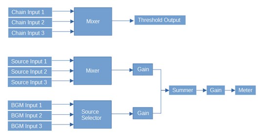
As you can see the chain inputs of each room are sent to a mixer then the threshold output of the Room Combiner. Essentially the Chain inputs are unmuted as the rooms are combined to create a common side chain.
Checking Use Automixer I/O on the Room Combiner processing object properties will expose Chain Inputs and Threshold outputs for the rooms.
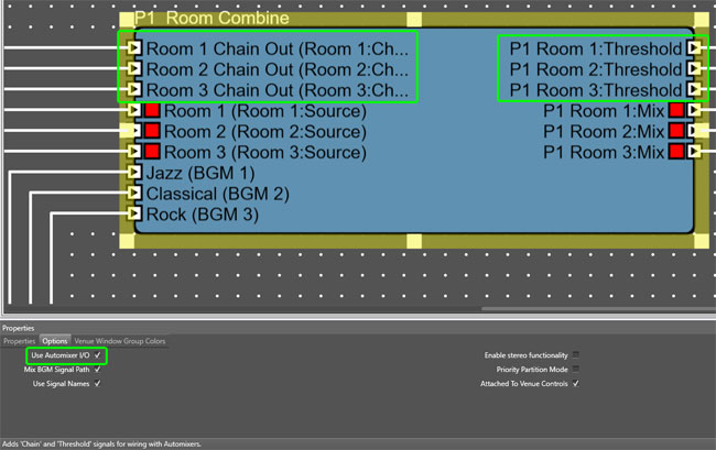
To use this feature, we will also need to setup the Automixers to slave off of the Room Combine. This is done in the Automixer properties.
This will expose a Chain In, Mix in and Threshold in as well as a Chain Output. Do this for each Automixer you are connecting to connecting to the room combine.
- Connect the Chain output of each Automixer to the Room Combiner Chain input (Orange Lines in Image).
- Connect the Room Threshold output on the Room Combine to the Threshold input on each Automixer (Green Lines).
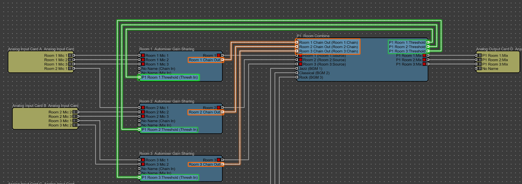
Now the Automixer will track when combined or uncombined with other automixers.
This gives the user the option of creating a separate output for the BGM path. Unchecking this exposes separate BGM outputs for each. This gives the designer the option of sending BGM to different outputs than the source audio.

Shows the Signal Names on the BGM input controls similar to a source selector.


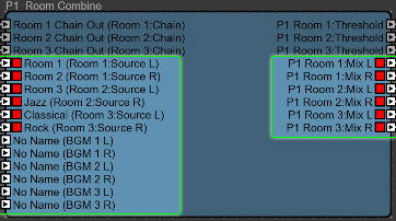
Useful in many cases where the rooms maybe setup in stereo. This can also be useful for conferencing where multiple audio sources are combined but not mixed together.
PRIORITY PARTITION MODE
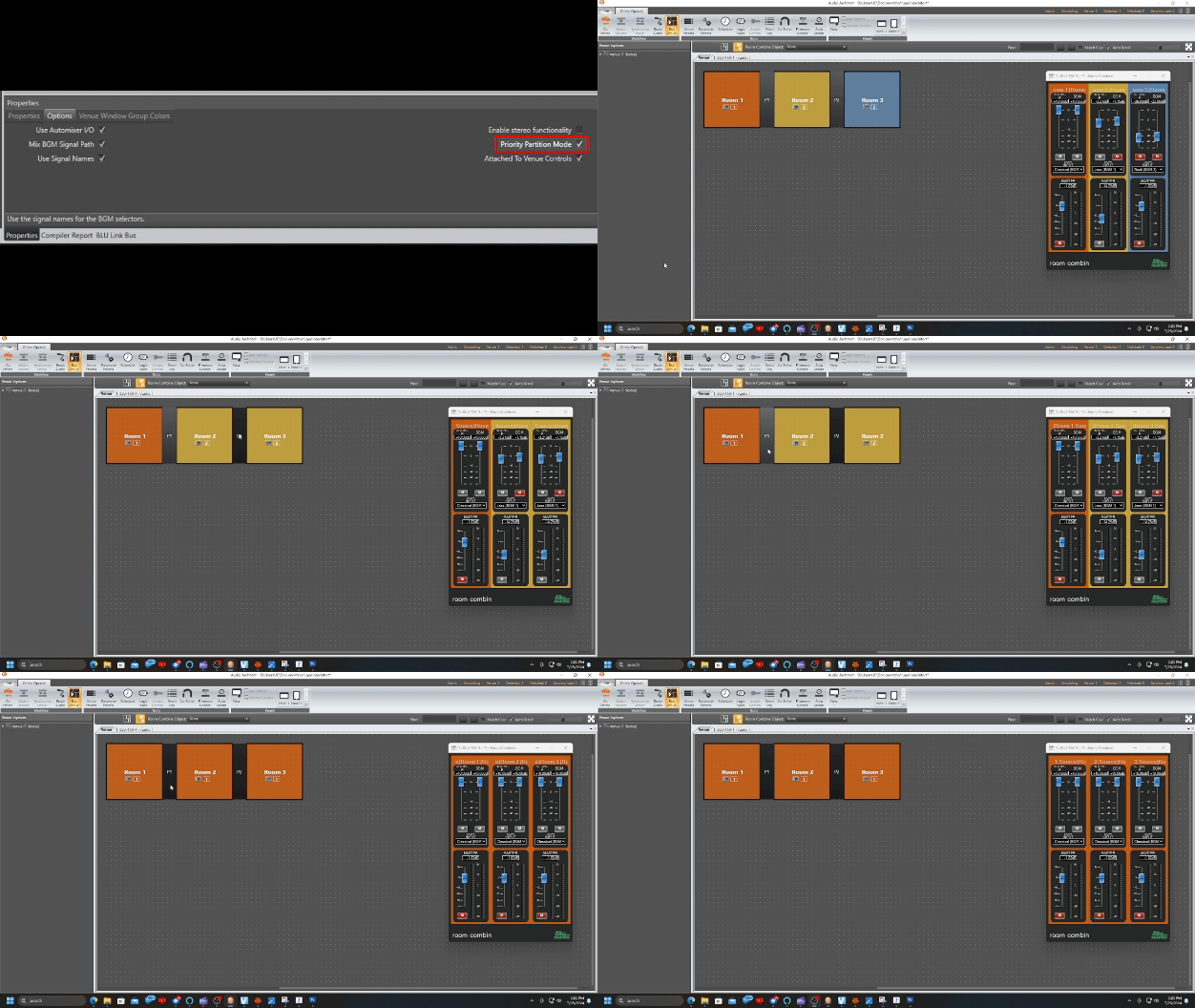
When this option is checked the lowest room settings are always used when multiple rooms are combined. This priority can be set when you first add the room combine object to your DSP. Once Priority Partition mode is selected, the room combiner will use the setting of the lowest room number when two rooms are combined. Thus if room 2 and room 3 are combined they will use the settings on room 2 for volumes, mutes and BGM. If rooms 2 and 3 are combined with room 1 they will use the setting of room 1. This mode is useful for scenarios where main functions take place in a particular area (lower room number) and you don’t want other rooms to override those settings. Another example might be a church where the chapel audio takes precedence over the overflow areas.
.
This allows you to disconnect the venue room controls from the controls on the venue window. Only use this option if you are using logic to drive the room combine and are having trouble with getting the correct feedback on the venue window controls.

Partitions parameters can be found in the design tree. These parameters can be linked to control inputs, assigned to presets, placed on control panels, or controlled via third party controlled.
Partitions can be dragged from venue explorer to a control input. This is useful if combining is controlled through a contact closure or IR sensor on an air wall.
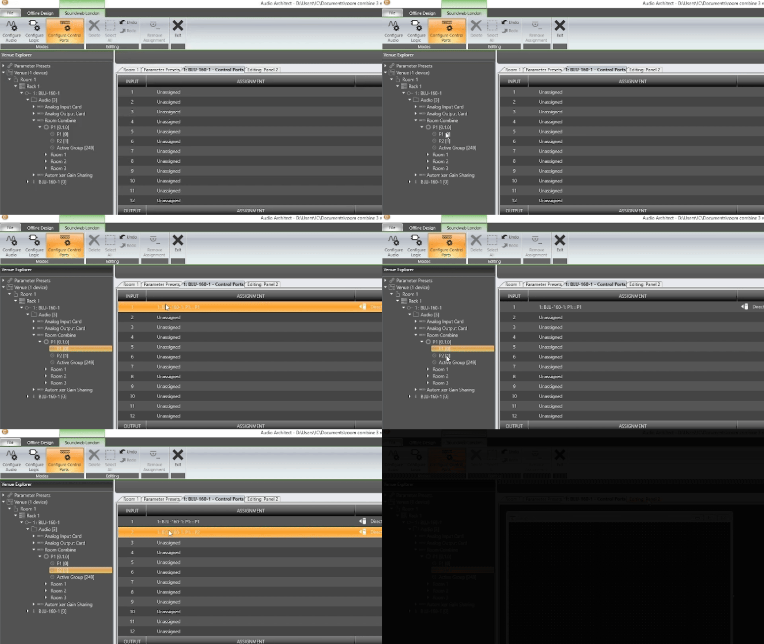
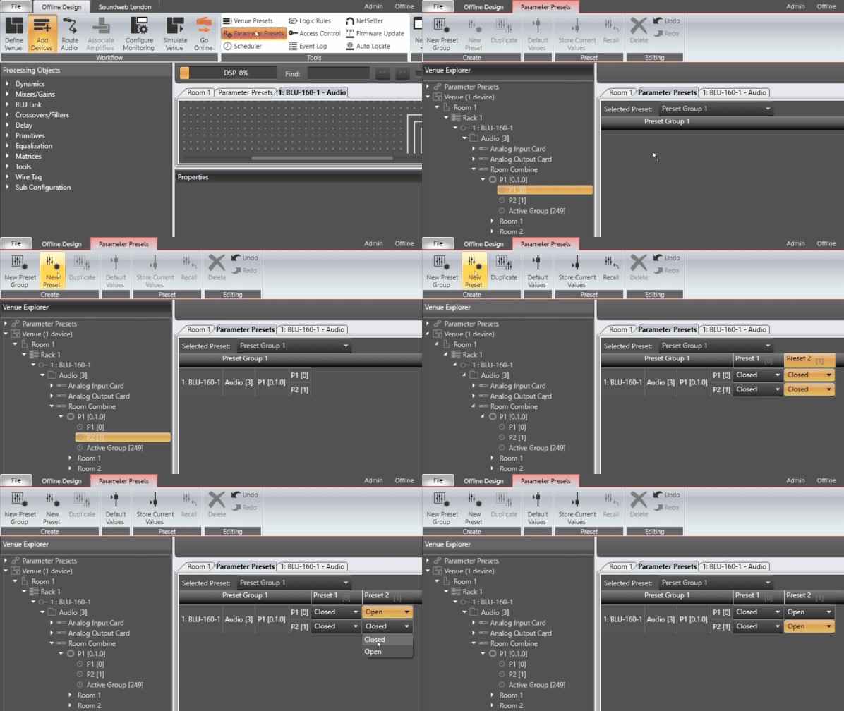
It is also possible to create presets to recall partition settings. To do this simply drag them into a preset group and then create your presets. Note: If you choose to use presets it is normally a good idea to recall either Groups or Partitions but not both.
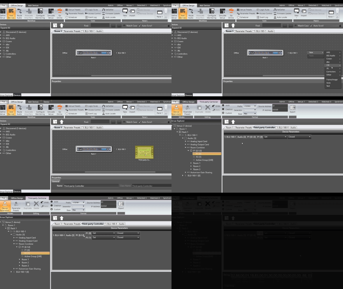
Using the AMX or Crestron Module you can simply enter in the object address information for Room Combine module and control partitions and groups. Partitions and Group numbers can be dragged into the Third-party Controller object to expose third party control strings as well. Note: to add a Third-party Controller to venue, right click in a room and select New>Controller>Third-party Controller. Then open the third party controller.
CUSTOM CONTROL PANELS IN AUDIO ARCHITECT
Partition and Groups can also be added to Control Panels in Audio Architect
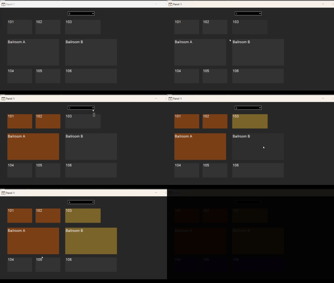
In this example Room Groups are assigned to the indicator on each region button and in Active Group is assigned to the button press for each room.
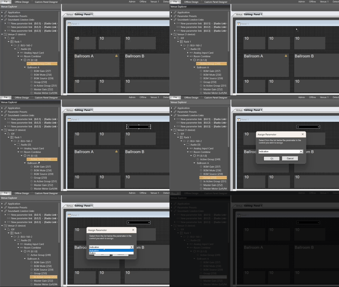
Clicking on a room assigns it to the active group. Clicking on a Room after selecting the active group will assign the room to that group.
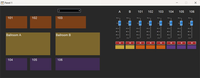
We can further add the volume and source controls from the default panel.
USING THE VENUE WINDOW FOR CONTROL.
The Audio Architect application itself also allows control of room combining via the Venue Window.
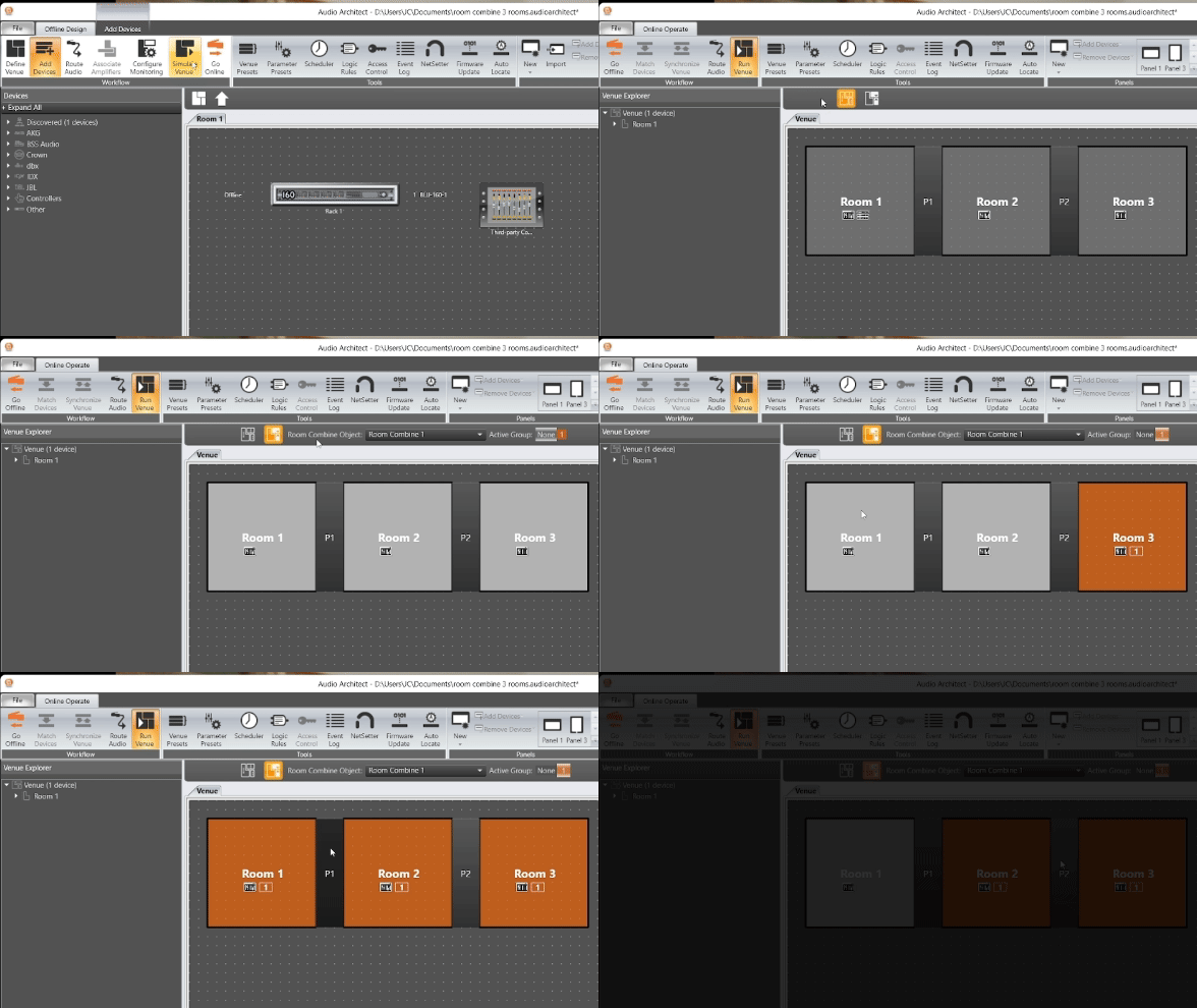
To active the Room Combine Mode, you must first go online with the processor. If you don’t have the hardware you can simulate the venue in the Workflow.
- Go to the venue tab and select the Room Combine mode button.
- Next select the room combine object you want to control.
- Use the partitions or groups to combine and uncombine rooms from the venue window.
ADVANCED TOPICS
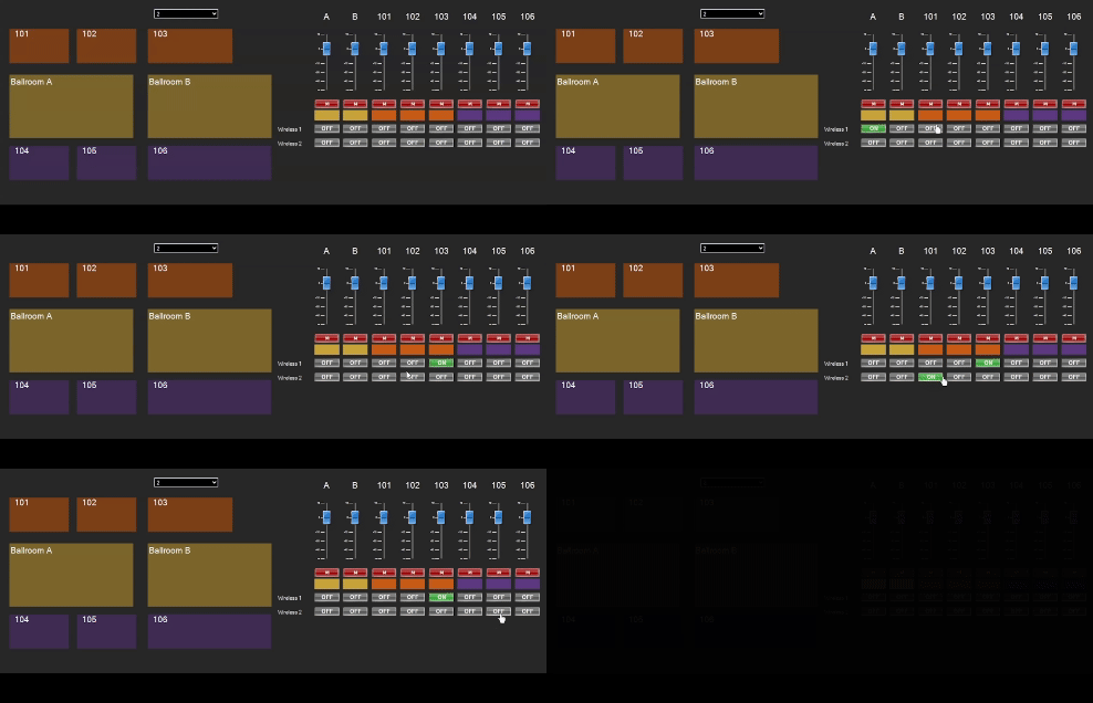
Some facilities have wireless microphones that can be used in various rooms. In this case you may want to use a matrix to assign the microphones to one room at a time. This prevents the microphone from being assigned in multiple rooms and changing the system gain through summing mixer together when combining rooms. In our larger room combine example microphones are fed into a matrix router. The output crosspoints on the router are then radio linked to that only one output is active at a time.
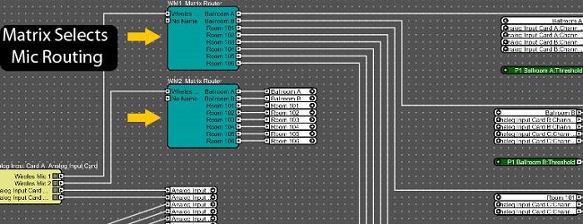

- Highlight all of the crosspoints for that sources outputs.
- Next select Radio Link with off
The microphone will now be exclusive to one particular output at a time. These controls can be placed on a custom panel or be controlled via third party control.
ROOM COMBINE IN CONFERENCING
In some cases, you may have conference rooms that can combined with other conference rooms. While this uses many of the same concepts it can quickly become much more complicated when trying to track references signals, AEC microphones and far side audio to the room. One easy solution to this is to use multiple linked Room Combine Objects to keep everything in sync.
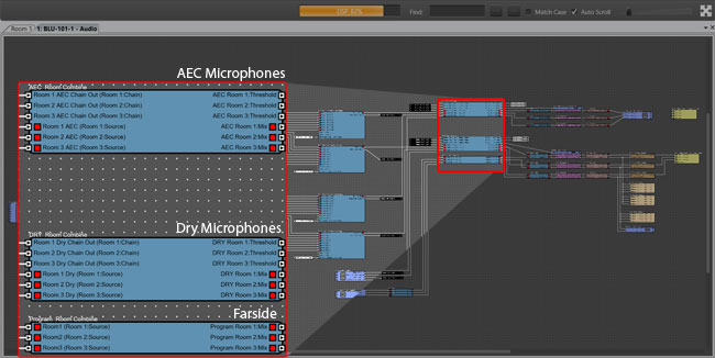
In this example we have three rooms with local Microphone reinforcement, AEC processed microphones and Far side audio all broken out to their own set to of Room Combine Processing Objects. To do this, multiple instances of the same Room Combine processing object can be dragged into the design. This allows combining of audio between multiple areas while keeping the signals separate for the AEC processed signals, Local Microphones and Farside audio.
These combiners can then be inserted to a signal flow.
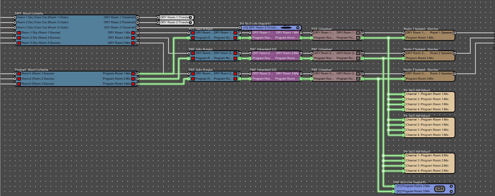
Notice there is a separate combiner for the Dry Microphone Signal and the Farside/Program Audio Combiner. Both signals are sent to the Room but we will only send the Farside Signal to the AEC Reference (highlighed in green). This is prevent referencing of the microphone audio.
Once we have added a room combine module for each of the signal types integrated we can link them together to make them work as a unit. This can be done in multiple ways either linking partitions and or linking the room groups.
Linking Partitions
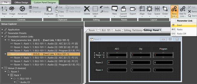
Each partition must first be added to custom panel to create the link. We are going to link Partition 1 or P1 on each module together with other P1 partitions from the other combiners. Each P2 will be linked with other P2 partitions etc. To make this easier to visualize we will label the Partitions on the custom panel.
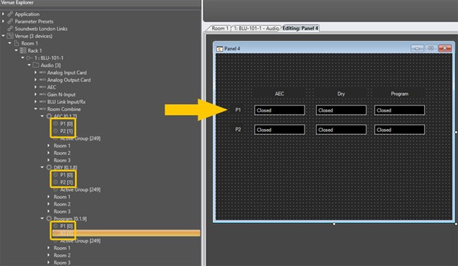
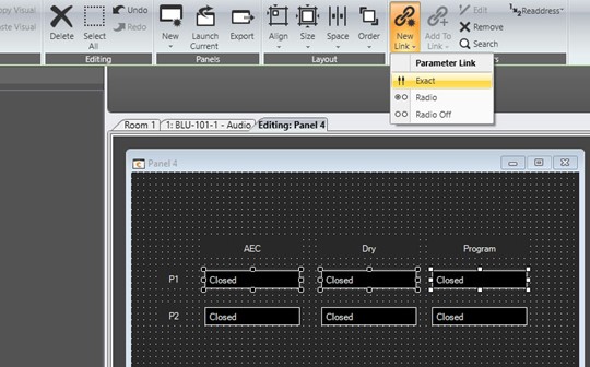
- Select each of the P1 partitions and select new link>exact.
- Repeat this step for each of the P2 partitions.
- The software will prompt you to create the link, click ok.
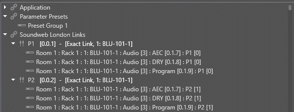
After creating the links, we can check the in the Venue Explorer.
Linking Groups
If you wish to use groups to combine each of the conference rooms you can use the same process but instead of linking Partitions link the Room groups between the Room Combine Objects.
Create the Custom panel this time with Room Group Controls.
- Link the Room 1 group in each Room Combine Object.
- Link the Room 2 group in each Room Combine Object.
- Link the Room 3 group in each Room Combiner Object.
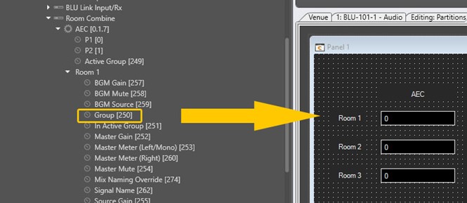
You can check them in the design tree.
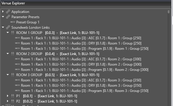
Once the Room Combiners are linked you can control any one of the through normal means and the other will stay in sync allow you to combine or divide the conference room. This makes complicated routing and logic that would take to keep track of all of these routes more automatic and allow you to spend your time on other things like tuning the rooms.