Basic Definitions of Antennas
Antennas can transmit as well as receive radio waves in a particular
frequency range
Properties of Antennas
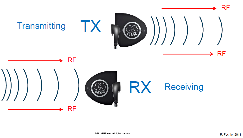
• A receiving antenna converts electromagnetic radiation (radio waves)
into an alternating current or voltage.
• A transmitting antenna converts an alternating current or voltage into
electromagnetic radiation (radio waves).
• Antennas are transducers that convert the electromagnetic wave from
free progressive waves into pipeline bound waves -or vice versa.
free progressive waves into pipeline bound waves or vice versa.
• All antennas have directional qualities. They do not radiate power
equally in all directions.
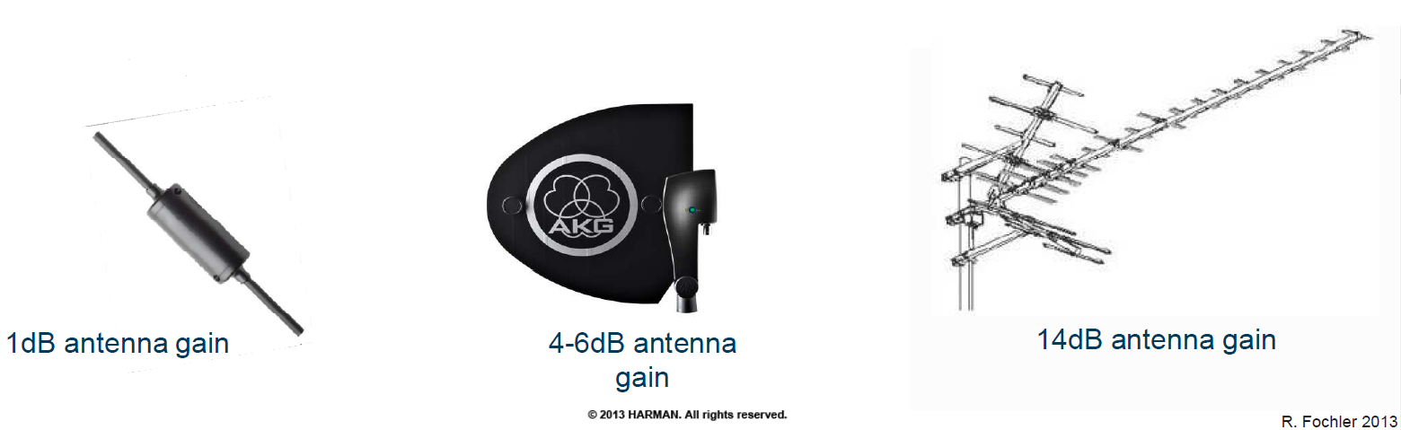
• The gain of an antenna increases with the amount of its directivity.
• Antenna gain and directivity are strongly related to each other.
Polarization of Antennas
• The polarization of an antenna is the orientation of the electric field of the radio
wave with respect to the earth‘s surface.
• Polarization can be vertical, horizontal or circular.
• It is determined by the physical structure of the antenna and by its orientation.
R. Fochler 2013
• It has nothing in common with the term „Antenna directionality“
• A linear polarized antenna (vertical or horizontal) radiates in one
plane containing the direction of propagation.
• In a circular polarized antenna, the plane of polarization rotates in a
circle making one complete revolution during one period of the wave.
Types of Antennas
• The physical construction of a antenna determines the
directionality of the antenna.
• The simpliest form would be a whip antenna, consisting of a single
straight wire or rod. Such antennas are omni directional, radiating in
all horizontal directions with the same power.
• The whip antenna is a „resonating“ antenna, therefore the length of
the whip antenna is determined by the length of the radio waves
used.
The dipole is a very common antenna and it is half a wavelength long.
This antenna works best when the waves arrive broadside.
Due to smaller housing sizes, the length of transmitter-and receiver
antennas are usually matched to ¼ of a wave length.
The higher the frequency range, the shorter the antennas!
• Yagi -Uda antenna
A dipole which shows a narrow directivity and a high antenna gain through an
array of directors and reflectors. The number of directors and theire length
determine the bandwidth and the frequency range of the antenna.
• Logarithmic Periodical Dipole antennas (Log Periodicals)
Array of dipoles connected with each other via a feeder line. The length and
spaceings of the elements increase logarithmically from one end to the other.
• More complex forms , variations of the dipole
Dipoles may be used as standalone antennas themselves, but
they are also employed as a feed antenna (driven element) in
many more complex antenna types, such as:
-Yagi antenna,
-Parabolic antenna,
-Log periodic antenna,
-Ground plane antenna
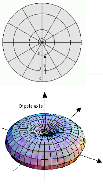
Antenna patterns
• Constructive elements can change the directivity of antennas
• To describe these qualities of directivity, there are 2 common forms to
line out the beamwidth in a plot
horizontal
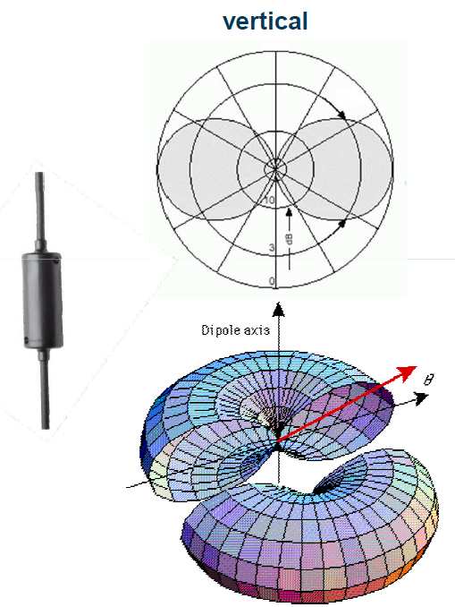
Evolution and Propagation
Magnetic field evolution of a vertical oriented Dipole
Antenna Gain
• An antenna's gain is a key performance figure which combines the
antenna’s directivity and electrical efficiency.
• As a transmitting antenna, the figure describes how well the antenna
converts electrical input power into radio waves headed in a specified
direction.
direction.
-Gain is needed for long distance radio links
• As a receiving antenna, the figure describes how well the antenna
converts radio waves arriving from a specified direction into electrical
power.
-Gain is needed to overcome long cable runs
• The ideal omnidirectional radiation from a point source would be an
isotropic antenna.
• Antenna gain is usually expressed with reference to an isotropic
radiator. (dBi)
• Antennas cannot create gain
• Gain is achieved by radiating more energy in some directions than
others.
• Total radiated power cannot be more than the power input to the
antenna
• Active elements like boosters can increase the gain of an antenna
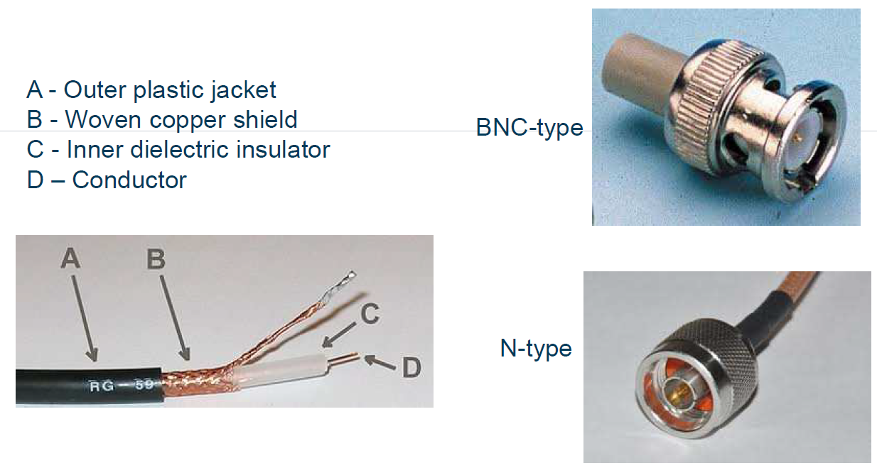
Antenna Cable
To remain quality and strength of a radio signal when converting from free-field into
cable bound signal, it is essential to use antenna cable and connectors that meet
certain specifications.
Antenna Cable Specifications
• Nominal Impedance
-usually 50ohms
• Velocity of propagation
-between 65 – 87% (of SOL)
• Capacitance
-between 75 – 95pF/m
• DC resistance
-inner conductor: 4-20ohms, outer conductor: 5-7ohm
• Attenuation
-0,5 – 0,1dB/m
Cable Attenuation
Cable length adjustment
Passive antennas connected to 5m RG58 going to the receiver
The input gain into the receiver should
be as close as possible to 0dB!
Passive antennas connected to 20m RG58 going to the receiver
The input gain into the receiver should
be as close as possible to 0dB!
Active antennas connected to 5m RG58 going to the antenna splitter
Active antennas connected to 20m RG58 going to the antenna splitter
RF gain attenuation is possible when
using an antenna splitter PS4000 / APS4!
Passive antennas connected to 20m RG213 going to the receiver.
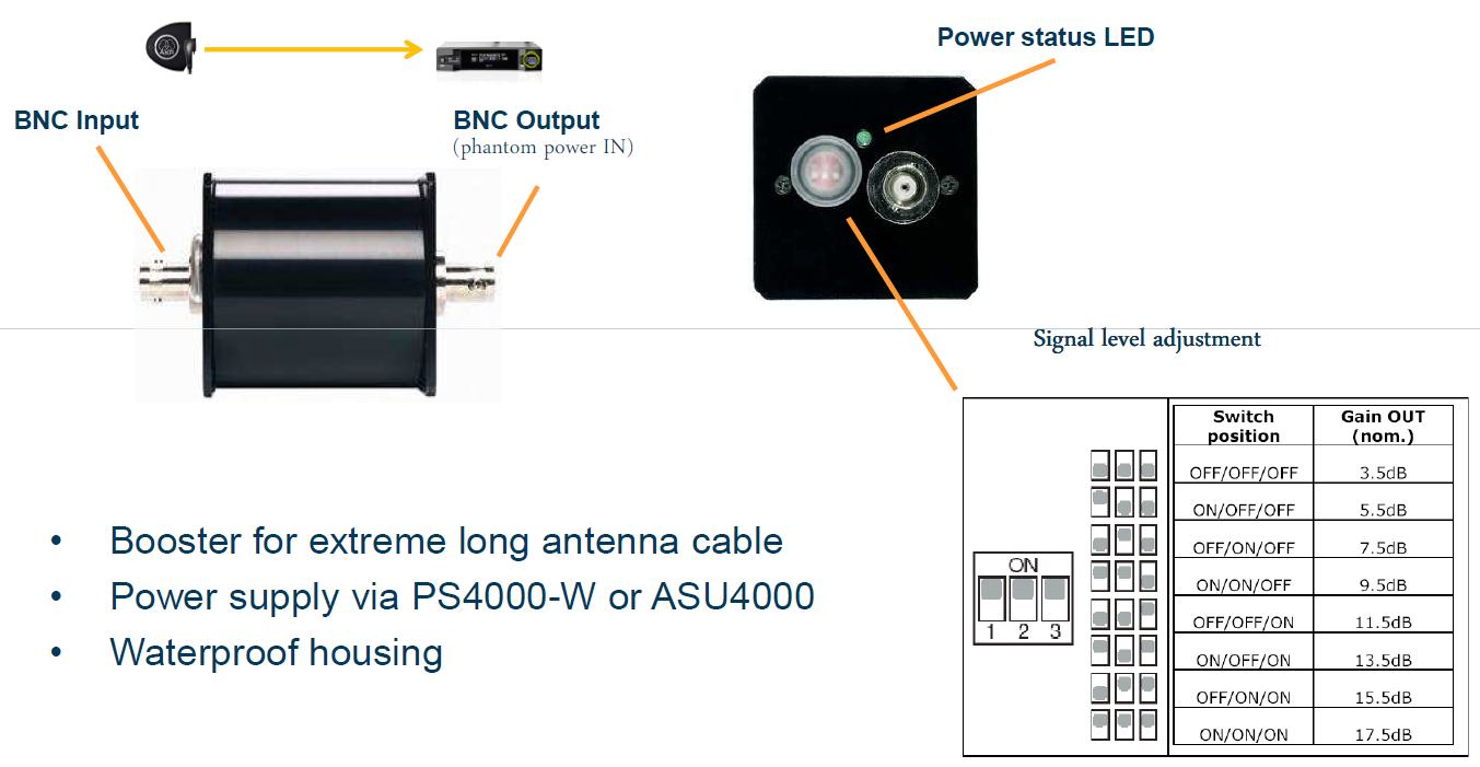
AB4000W – Antenna Booster
ASU4000 – Antenna Supply Unit
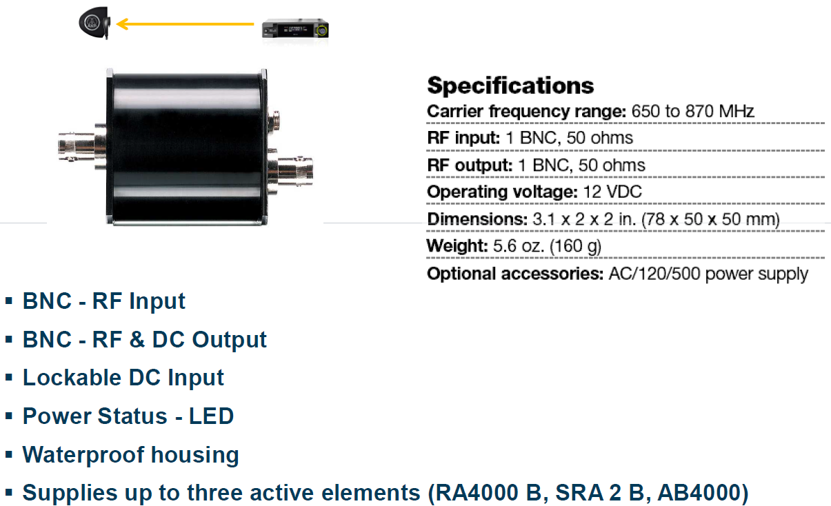
• Supplies up to three active elements (RA4000 B/EW, SRA 2 B/EW, AB4000, AB4000 EW)
Cable length adjustment
SRA2 B/EW Antenna + 100m cable RG58
Antenna cable calculator
Common cable types and their attenuation figures:
