Contents
Intro
Local I/O
Wiring
One to One
One to Many
Wire tags
Processing Object Mute Indicators
Source Selectors
Mixers and gains.
Matrices
Side Chains
Network I/O
BLU link
CDI AMplifiers
DCI Amplifiers
Dante
Other protocols
AVB
CobraNet
Putting it together –Sample design.
Tracing an Audio Signal is a necessary skill in designing, commissioning and troubleshooting a system. There are a few tools in the Audio Architect Software to help you do this. This guide will cover the how to navigate the signal flow in a BSS Audio System and give you some insight how the system connects to other devices.
The first thing to understand is how the audio gets in and out of a processor. Audio come and leaves through I/0 blocks. These blocks can be Local I/O which is part of the physical processor or they can Network I/O. We will cover both.
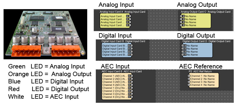
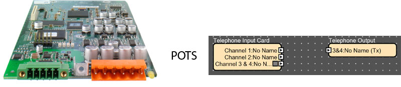
Local I/O blocks representative of the actual physical ports on the box. These include analog inputs/outputs, Telephone (VoIP and POTs), AEC (acoustic echo cancelation analog card) and digital (AES/EBU)

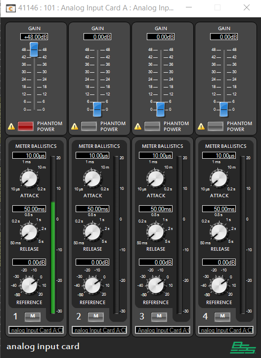
Opening a Local I/O block will show you meter indicator. This is a good place to look and see if the processor is sending or receiving audio. Note: the meter starts at -30dBu, so if the signal is weaker such as a microphone you might not see any signal on the meter if it is quite weak. We recommend bring the source up to full and then adjust the input trim until the audio is around 0dBu to get the best signal to noise ratio. There is 48dB of gain available on each input which is usually more than sufficient for most sources.

Once inside the DSP we also hover over a wiring when online. This will produce a dynamic meter. Each DSP allow two dynamic meters by default. To use a dynamic meter simply hover over a wire while online. This will give you a meter indication showing the level of the signal going through the wire. This is a great way to trace a signal through a DSP. Selecting the arrow will pin the meter and let you assign a second meter elsewhere.
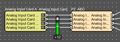

In this case I can see that my signal is a little hot so I could bring the input trim down a bit and be just fine.
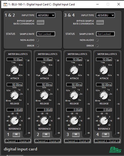
Different types of local I/O have different control panels based on the type of signal. Digital Cards have a control panel showing sync as well as a meter. Notice there is not a trim control because the control is already digital.
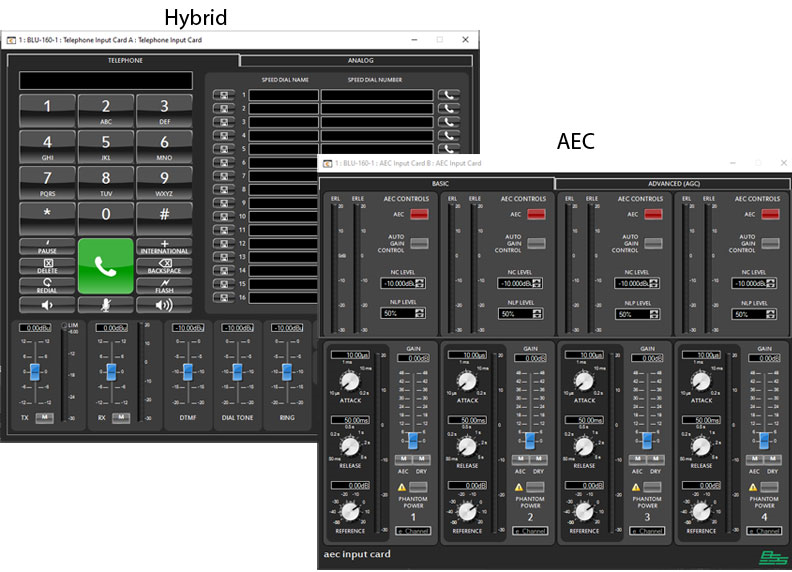
The VoIP and Hybrid cards have a dialer and the AEC card has the AEC settings. The Hybrid and VoIP cards have meters for both the input and output built on the input card control panel. This is because the Audio is bidirectional on those interfaces.
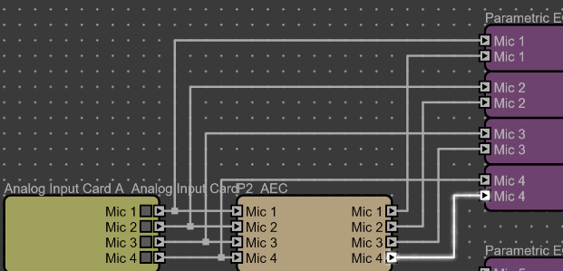
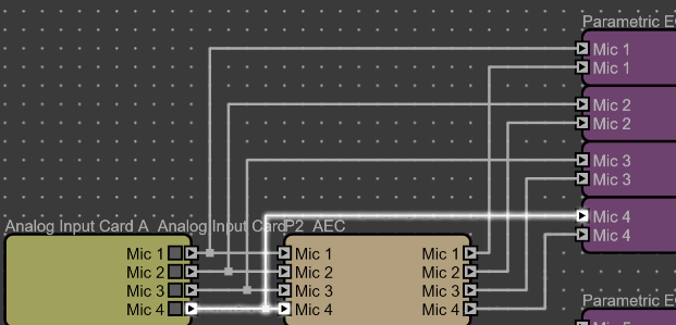
So now that we understand how audio gets in we can look at how audio interconnects within a processor. Wiring represents signals routed within the DSP between objects. The general rule of wiring is you can split signals to multiple objects however you must use a mixer or summer to combine signals. Wired signals from outputs can go from one object or be split (one to many).
One to One


Wire tags are basically a short hand way of making a wired connection inside a DSP. The name of the signal is populated on the both the transmitting and receiving wire tags. Selecting the arrow will take you to the wire tag on the other end. If there is more than one destination, Audio Architect will ask you which one you want to follow based on the processing object it connects to.

Source Matrices and Source Selectors will show a red indicator on the output if none is selected for the source indicating the processing object is not passing audio on that output.

Also notice that you will see the signal name appear on the output when it is assigned. For more info see Signal Naming.
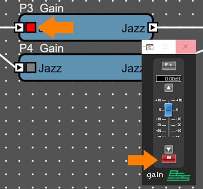
Mixers and gains will show mute indicators for the input and output mutes when channels are muted.
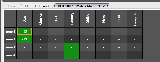
Matrix Mixers and Matrix routers have to be opened to see their routing. Green cross points indicate audio is routed, while grey cross points indicate audio is muted. To change a cross point simply select it and press enter.

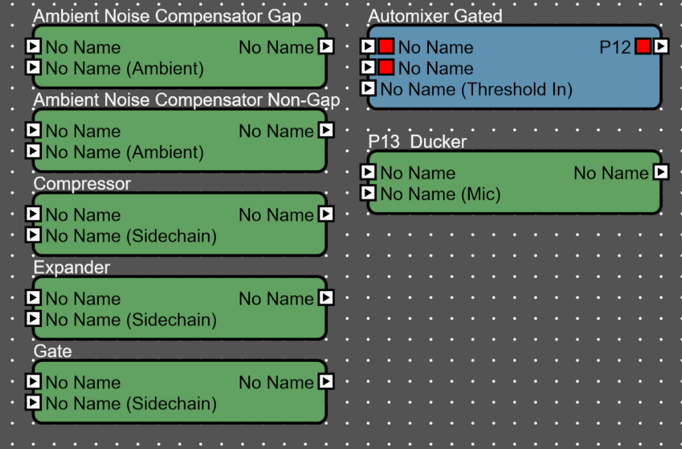
Objects with side chains have a special input signal that is
used to control the other channels. The first input is passed to the output
with processing applied. The lower input is used as a side chain or control and
is not passed to the output. Sometimes this signal is labeled sidechain, or
threshold or ambient or mic.

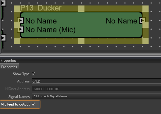
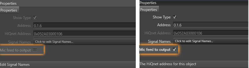
In the case of the ducker it is optional to mix the input signal to the output i.e. you want to hear a microphone ducking music. For this to happen you must check the "mic feed to output" option.
Network I/O
In addition to the local I/O on a box, audio can also enter and leave the system via the network audio ports. These include BLU link, Dante (AEAS67), AVB and CobraNet.
BLU link is the HARMAN proprietary protocol that allows DSP and Amplifiers to share audio. BLU link shows up as its own type of port. It enters and leaves via the BLU link connectors on the back of the processor. These can connect to other devices including Crown Amplifiers, BLU-USB, BIB/BOB Expanders, Soundcraft SI Mixers and of course other DSPs. BLU link is different than that other Network protocols in that it connects directly to other devices and doesn't go through a switch.
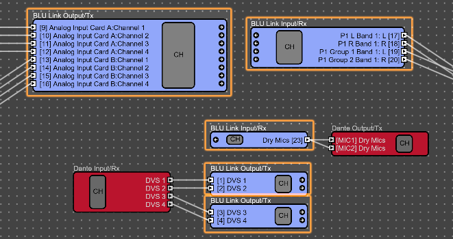
BLU link Transmitters (Tx) and Receivers (Rx) are represented by the blue processing object blocks.
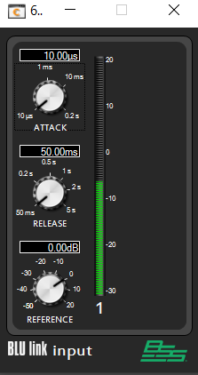
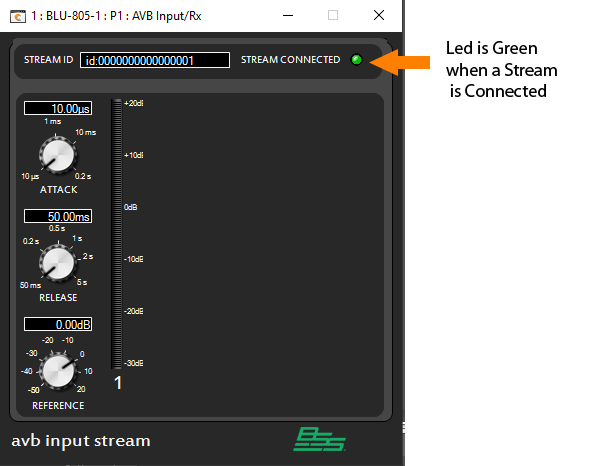
Opening the BLU link I/O block looks similar to an input/output card. The controls on the left (Attack, Release and Reference) adjust how the meter reacts to the audio. Normally the reference should be 0. Lowering reference can useful when troubleshooting low level noise that doesn't have enough signal to show up on the meter.

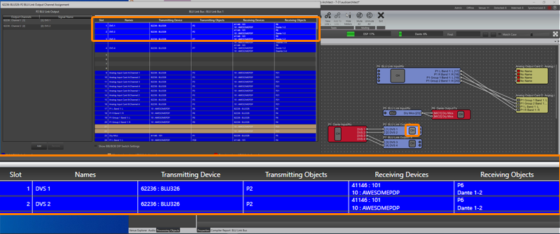
Selecting the CH button on a BLU link block will open the routing window which will display all of the places the BLU link signal is routed to.
When a BLU link transmitter has a receiver assigned the processing Block will show an arrow at the end of the Block. Clicking on this arrow will take you to the receiving device. If there is more than one Device receiving then you will have the option of which device you want to follow the signal to.
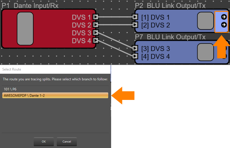
Clicking ok will then take you to the DSP receiving the BLU link. You can use the same process at the receiver by selecting the Arrow on the receiver to take you back to the transmitter. This can be a handy way of navigating the signal flow in a large complex design using BLU link.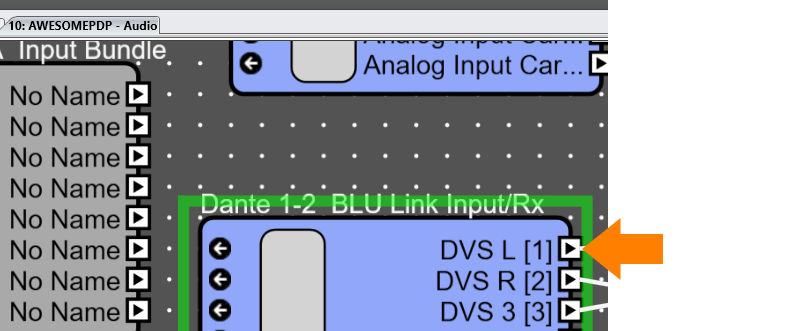
Crown Amplifiers also use BLU link. On an amplifier the BLU link is displayed as channel numbers. The channel numbers of the receiver simply need to match the transmitter.
Devices that use dipswitch setting to set their audio channels such as BLUBIB, BLUBOB, BLUUSB and Soundcraft UI do not show up in the routing in the software. These devices require checking the physical dipswitches at the device.


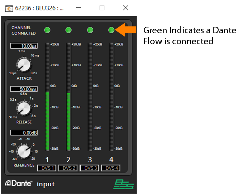
Dante transmitters and receivers are represented by the red processing object blocks These blocks are available in any of the Dante enabled DSPs including the BLU806, BLU326 and BLUDA. Dante is a layer 3 Network Audio Protocol that can travel across a standard IT network.


Dante uses flows on the network to connect audio paths together. The control panel for the receiving Dante block will show the standard meter along with information telling you if that the flow is connected or not to a transmitter. If the flow is connected, it indicates that you are able to receive audio over the network on the connected channel. If the flow is not connected that could indicate that the requested stream from the transmitter is not available on the network or the Dante flow has not been configured.
Inputs and outputs are routed using channel names. These names are pushed to the Brooklyn II card when you load a device along with the device name and the processing Block name. You can see these flows in Dante Controller. The receivers are on the left and transmitters are on the top. The device name tells you which device is receiving or sending the audio along with the Processing Object Name and the Channel Name.
 In addition to showing the flows being connected, Dante Controller will also has meters built in. By opening the device you can see if the Brooklyn card is actually transmitting or receiving audio by looking for the green speaker icon indicating real audio is actually playing.


Other protocols
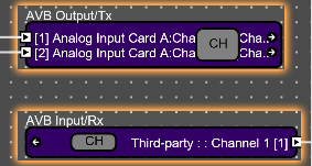
Audio Video Bridging is not as common as Dante but it works similarly except that the audio is grouped into streams and the network switch manages bandwidth. Streams can also be monitored using third party software such as Riedel AVB Manger. For more information check out the HiQNet network audio document.
CobraNet was once was the standard for Network audio and the most common protocol. It is still used in many older installs. CobraNet is a layer 2 protocol so it goes through switches. CobraNet packages audio into 8 channel groups called bundles. Typically a CobraNet card will handle 4 input bundles and 4 outputs bundles for a 32x32 configuration. Bundles are configured either unicast (one transmitter and one receiver) or multicast (broadcast everywhere).
Similar to previous network protocols the CobraNet block has a meter and will show you if the Bundle is being received.
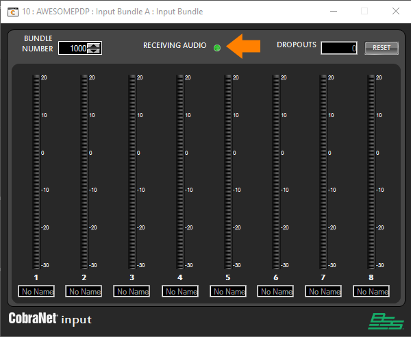
The bundle number is like a stream, when the transmitter bundle matches the receiver bundle audio will flow. You can also check the status of CobraNet using the CobraNet Discovery (Disco) Utility available from Cirrus Logic.
https://www.cobranet.info/downloads
In this sample Design we will cover tracing audio from a Dante Paging Source at the main rack room through the DSP to an amplifier and show possible resolutions to some sample problems.
In the first example is based on a report that the customer is not getting paging audio from their microphones. Here we will trace the microphone signal from the begging through each stage of the system to find where the audio is broken.
This design uses Dante to distribute the microphone audio and BLU Link to connect the DSP to the amplifiers.
Starting at the begging of the chain we know that the microphone cable is connected to a BLU3267 labeled BLU326. We can first see the input signal enter the DSP in the main rack room on input Card A channel 1. We know this be the signal name for the microphone has been entered on the input card.
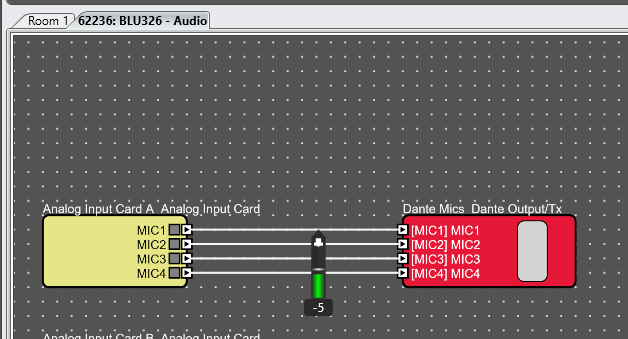

If we measure the signal we can there is audio. Since the audio goes imediatley to a Dante Tx, I can check the signal in Dante Controller.


Here I can see that Microphone 1 is routed from BLU326 to BLU326-2.
Opening the receiving device shows us audio is received.


Open the receiving device in Audio Architect and we can see audio coming in and then going out on BLU link.
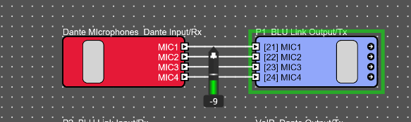

Selecting the arrows at the end of the block will take to the receiving BLU link DSP.

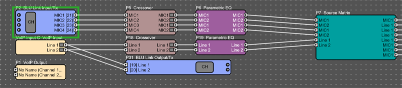
Here this signal enters passes through a crossover (used for high pass filter and limiting) then an EQ and then to a source matrix. The source matrix happens to be controlled from a control system and we can see by the signal names that MIC 1 is routed to the first output as well as outputs 6, 7 and 8. If a paging problem was related to the control system affecting paging we might expect to see it here where the signal is routed.
We can also use the dynamic meter to see the signal at any point.

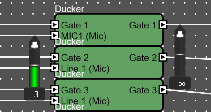
Following the Source Matrix to the output we can see the microphones go into the microphone side of a ducker. When hovering over the output of the ducker we can see that there is no output even though there is input signal.
Further investigation show that Mic feed to Output is not checked in the properties of the ducker. To make this change we simply need to go offline and then check the box.
After going back online and loading the change we now see the microphone is passing through the ducker.
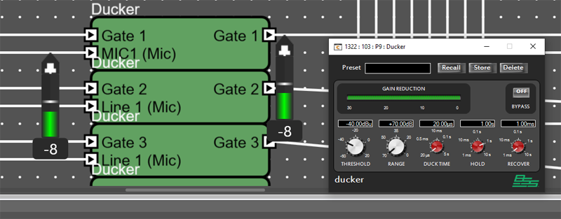
Opening the ducker we can see the gain reduction meter show us that the ducker is active. This is because the microphone level is peaking above the ducker threshold. At this point you have a made a change to the system and so the issue may be resolved. Let's say we are remotely connected to the system therefore we will need to verify the signal all the way to the amplifier.
The signal then enters the Ambient Noise compensator.
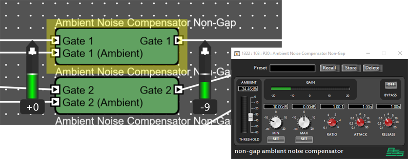
Since there is very little sound coming in on the ambient Microphone the output is reduced approximately 10 dB on the output which is related to the minimum gain setting.
From here the signal flows through a gain object and out to BLU Link. There is also an AEC reference object but that doesn't affect this signal since paging doesn't route through AEC.


Clicking on the BLU Link Arrow doesn't take me anywhere. That is because this single happens to be routed to an amplifier at this point. To see where the signal is routed at this point we can either go offline and open the BLU Link TX channel assignment or select the route audio mode. Selecting the Channel in the route audio mode we can then select the BLU Link signal in the route audio mode will show a B indicator on each amplifier that the signal is routed to.
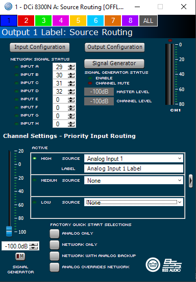
If we know which amplifier we are expecting signal at we can simply open the amplifier control panel and verify signal knowing we are looking for BLU Link Channel 29.

 Opening the amplifier shows us signal on the input of the amplifier but no output signal.
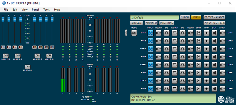
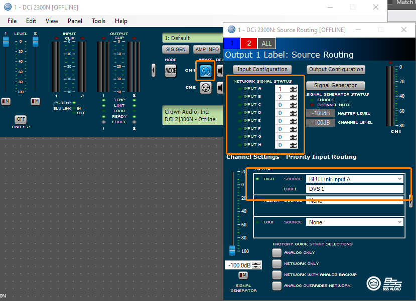
Opening channel 1 of the amplifier shows the BLU link signal coming in but we can see the output is assigned to analog instead of BLU link. Changing this to BLU link input A completes the signal flow out to the speaker.
| 
|
