Definition of a Multi Channel System (MCS)
A Multi Channel System is referred to as:
• More than 4 channels of wireless links between TX –RX (WMS or IEM)
• A common antenna system for all connected wireless channels
• A central power supply for all connected devices
• Coordinated frequency managment within a certain bandwidth
• Often software based control of all connected devices
Individual versus common supply
8 channel system with individual
lapel antennas and single in-line
PSUs (power adapters)
8 channel system with common
antenna system and central PSU
R. Fochler 2014
Antenna Splitter
Essential device when building a multi channel system
• When using an antenna splitter, the incoming antenna signal gets split into
multiple feeds, to supply multiple connected receivers with sufficiant RF signal.
• Some antenna splitters are able to supply voltage to the connected receivers.
=> no additional PSU is needed.
• Some antenna splitters are able to regulate the incoming RF signal strength.
=> optimized RF gain structure.
Antenna Splitter PS4000-W
• The antenna splitter PS4000-W provides 8V DC on the antenna inputs A/B
to feed sufficient power via the antenna cables when connecting active
antennas.
• All receivers will be powered via the antenna patch cables with 12V DC when
connected to the antenna split outputs 1-4.
• Up p to 3 antenna splitters sp can be linked to distribute the direct incoming g
antenna signal
• There is no voltage provided at the link o/p!
Antenna Splitter RF gain adjustment
The incoming RF gain can be adjusted according the cable type,
cable length and type of connected antennas, to optimize the performance of all connected receivers
The PS4000-W dip swich selector will reduce the RF level of the
antenna input by 0 -14dB in steps of 2dB
• The selected attenuation will reduce RF levels on all antenna outputs as well as on the link out A/B.
• The first splitter is connected to the antennas, so this is the relevant one to attenuate the RF signal.
• If there are two ore more antenna splitters linked to the first one, the RF level
is to adjust only at the first splitter, all linked ones should be set to 0dB attenuation!
• In a 16 channel WMS system with 4x antenna splitters also the PS4000 that
gets the split antenna signal needs to be adjusted.
It is essential to adjaust the incoming RF gain in order to run
approx. 0dB into the receivers.
• Active antennas deliver more gain than passive ones
=> different gain settings on antenna splitter dip switches
• Good quality Low loss antenna cable preserves more gain than standard RG58 cable of the same length
=> different gain settings on antenna splitter dip switches
• Long antenna cable runs – short antenna cable runs of the same quality
=> different gain settings on antenna splitter dip switches
Antenna Splitter PS4000-W
Supplying the antenna splitter with adequate power is important
for stable functionality of all connected devices.
PS4000-W / PSU4000 with 2 receivers
Up to 4 receivers can be connected and supplied with current if
the antenna splitter is powered by the PSU4000.
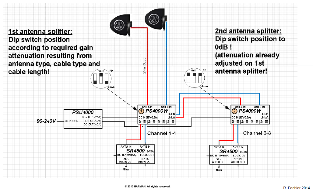
�1 PSU4000 can feed 3xPS4000-W
2 channel system example, receivers powered via antenna patch cables
Linked antenna splitters for 8 channel WMS
2x PS4000-W are linked for a total of 8 channel WMS
Linked antenna splitters for 8 channel WMS
Linked antenna splitter for 12 channel WMS
3x PS4000-W are linked for a total of 16 channel WMS
Linked antenna splitters for 12 channel WMS
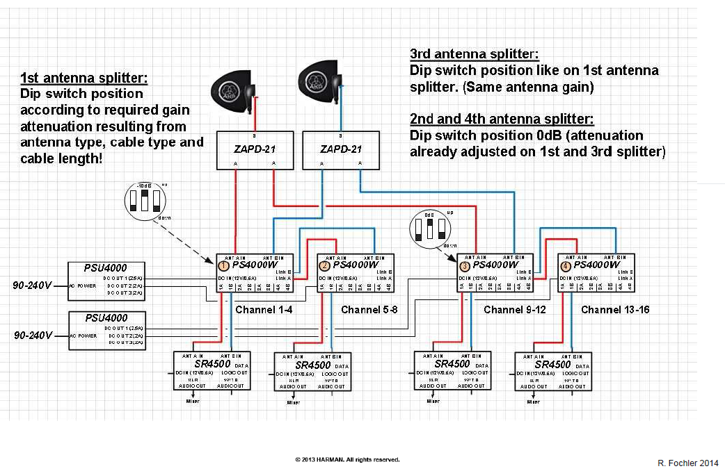
Linked antenna splitter for 16 channel WMS
4x PS4000-W are linked for a total of 16 channel WMS
Main antenna in A/B is split passively and feeds PS4000 1+3,
PS4000 2+4 is fed by link o/p from PS4000 1+3
16 channels WMS with 4 antenna splitters
Passive Splitter / Combiner
Antenna signal split into two antenna splitters PS4000-W
�Multi antennas combined into one splitter PS4000-W
PS4000-W / PSU4000 with 5 receivers
Even though a PS4000-W is designed to fully support 4x receivers with
antenna signal and sufficient power, a 5th receiver may be connected.
• The 5th receiver needs to be powered separately!
5 receiver on 1 PS4000-W
Aspects of frequency and RF power in MCS
Rule of the thumb: more wireless channels – less RF power
�Use robust frequencies from preset lists for IM free operation
�Use reduced radiation power if TX-antenna distance is not of importance!
Aspects of frequency and RF power in MCS
High ERP (Effective Radiated Power) will increase the number and
the strength of IM products => reduced clean spectrum
Aspects of frequency and RF power in MCS
The Near – Far Ratio
�The NFR (Near-Far ratio) is referred to as the difference of the shortest
distance and of the longest distance from transmitter to antenna.
�Due to high reception level from near transmitters there might be strong TX-
TX Intermodulation that could override the lower level signal from the far transmitter
If TX3 is close to the antenna, its signal is strong enough to overrule the IM product and transmit stable on F3
If TX3 gets far away from the antenna, its signal will get too week and the IM product will disturb stable transmission on F3
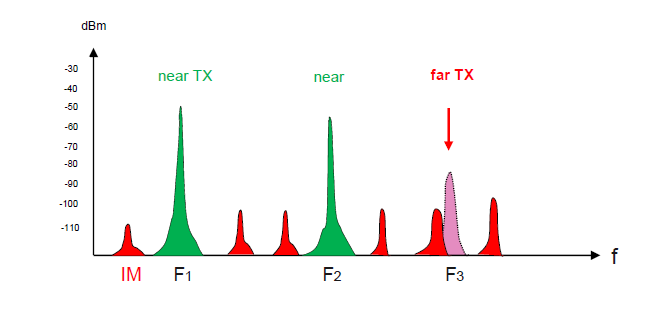
To maintain stable transmission, the carrier has to be at least 20dB stronger than any IM product!
Aspects of frequency selection in MCS
If the carrier to carrier distance is too small, there will be noise generated due
to overlapping zones in the base of the carriers
�Keep a distance of at least 300kHz (carrier grid)
Multi Channel setup
Before the transmitters are swiched on, the receivers with their
programmed frequencies should be checked for their exclusive
unoccupied status.
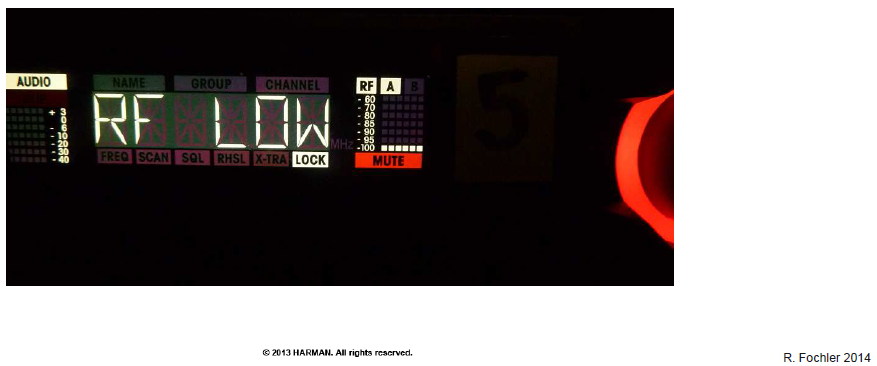
If none of your transmitters is switched on, this is how your
system shoud NOT look like!
If receivers are sensing unwanted RF there is a disturbing 3rd party
signal close or at the same frequency of your channel allocation
RF status shows two different possibilities:
�Designated transmitter is OFF but receiver is sensing unwanted RF signal.
�Designated transmitter is ON but out of sufficient field strength.
Squelch level adjustment
Adjust the squelch level so that it is slightly above the RF noise
Noise level -95dB, squelch -98dB
=> Audio stays unmuted
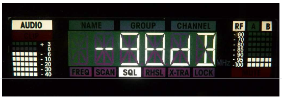
Noise level -95dB, squelch -94dB
=> Audio stays muted
Multi Channel rack positioning
A rack with HF equipment should be placed isolated from any
radiating or vibrant electronical circuitries, such like
• Dimmer racks
• LED-walls and their control module
• Laptops, monitores
• Unshielded electric motors, spark generating devices
• Electrostatic charging
…and they should be located in a well tempered location with
normal humidity.
Multi Channel System example
Madrid rehearsals
Taipei Opera
Open air stage Life Ball, Vienna
Thank you for your attention!
