Electric-power companies have a good idea which has been applied to audio engineering. When they run power through miles of cable, they minimize resistive power loss by running the power as high voltage and low current. To do this, they use a step-up transformer at the power station and a step-down transformer at each customer's location. This reduces power loss due to the I2R heating of the power cables. The same solution can be applied to audio communications in the form of a Constant-Voltage System (typically 70 volts in the U.S. and 100V overseas). Such a system is often used when a single power amplifier drives many loudspeakers through long cable runs (over 50 feet). Some examples of this condition are distributed speaker systems for P.A., paging, or low-SPL background music:
 Figure 1. A typical high-impedance system using a step-up transformer on the amplifier output
There are three options at the power-amp end for 70V operation:
• an external step-up transformer
• a built-in step-up transformer
• a high-voltage, transformer-less output
These options are covered in detail later in this article.
The signal line to the loudspeakers is high voltage, low current, and usually high impedance. Typical line values for a 100-watt amplifier are 70V, 1.41 amperes, and 50 ohms.
How did the 70V line get its name? The intention was to have 100V peak on the line, which is 70.7V rms. The technically correct value is 70.7V rms, but "70V" is the common term. There are 70 volts on the line as maximum amplifier output with a sine wave signal. The actual voltage depends on the power-amplifier wattage rating and the step-up ratio of the transformer. The audio program voltage in a 70V system might not even reach 70V. Conversely, peaks in the audio program might exceed 70V.
Other high-voltage systems might run at other voltages. Although rare, the 200V system has been used for cable length exceeding one mile.
Advantages of 70V operation
As stated before, a 70V line reduces power loss due to cable heating. That's because the speaker cable carries the audio signal as a low current. Consequently you can use smaller-gauge speaker cable, or very long cable runs, without losing excessive power. Another advantage of 70V operation is that you can more easily provide the amplifier with a matching load. Suppose you're connecting hundreds of speakers to a single 8-ohm amplifier output. It can be difficult to wire the speakers in a series-parallel combination having a total impedance of 8 ohms. Also it's bad practice to run speakers in series because if one speaker fails, all the speakers in series are lost. This changes the load impedance seen by the power amplifier.
With a 70V system you can hang hundreds of speakers in parallel on a single amplifier output if you provide a matching load. Details of impedance matching are covered later. In addition, a 70V distributed system is relatively easy to design, and allows flexibility in power settings.
Let's compare a standard low-impedance system to a constant-voltage system. Imagine that you want to provide PA for a runway at an airshow. A low-impedance system might employ 30 speaker clusters spaced 100 feet apart, each cluster powered by a 1000W amplifier for extra headroom. A high-impedance version of that system might use only one amplifier providing 140V. The cost savings is obvious.
Disadvantages of 70V operation
One disadvantage of a 70V system is that the transformers add expense. Particularly if you use large transformers for extended low-frequency response, the cost per transformer may run $70 to $200. Low-power paging systems, or those with limited low-frequency response, can use small transformers costing around $4.95 each. Many loudspeakers are sold with 70V transformers included.
Another disadvantage is that transformers can degrade the frequency response and add distortion. In addition, a 70V line may require conduit to meet local building code.
Transformers
The main component of a 70V system is the speaker transformer. Its secondary winding has taps at various impedances. You choose the tap that matches the speaker impedance. For example, if you're using a 4-ohm speaker, connect it between the 4-ohm tap and common.
The primary winding has taps at several power levels. These power taps indicate how much maximum power the speaker receives. For example, suppose you have a 70V transformer with the primary tapped at 10W and the secondary tapped at 8 ohms. Then a loudspeaker rated at 8 ohms should receive 10W at its voice coil when the primary is connected to a 70V line.
Transformers have insertion loss mainly due to resistance. Precise system calculations should take insertion loss into account. These calculations are covered in the Appendix.
Crown's Commercial Audio series of amplifiers and mixer-amps provide both low-Z and constant-voltage operation. For example, the 180MA and 280MA mixer-amps offer 4-ohm, 70V and 100V outputs.
Installation
With this background in mind, let's proceed to installation practices. Here's a basic procedure that neglects transformer insertion loss:
1. Do NOT connect the 70V speaker line to the power amplifier yet.
2. Install a transformer at each speaker location, or use speakers with built-in transformers.
3. Connect each speaker to its transformer secondary tap. The tap impedance should equal the speaker impedance.
4. Connect each transformer primary to the 70V line from the power amplifier. Choose the tap that will deliver the desired wattage to that speaker.
5. Add the wattage ratings of all the primary taps. This sum must not exceed the amplifier's wattage rating. If it does, change to a lower-wattage primary tap of one or more transformers, or use a higher-power amplifier.
6. Connect the 70V speaker line to the 70V output of the amplifier.
As an example, suppose you are setting up a 70V system with 8-ohm speakers and a 60W power amp.
Connect the 8-ohm secondary taps to each speaker. Suppose the total speaker wattage is 55 watts. This is acceptable because it does not exceed the amplifier power rating of 60 watts.
Here's a more detailed procedure that emphasizes impedance matching:
Compute the minimum safe load.
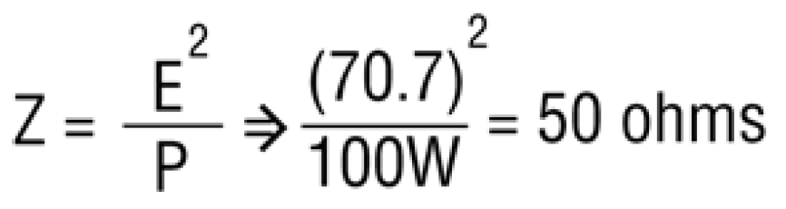
The minimum safe load impedance that can be connected to the amplifier is given by:

Where
Z = minimum safe load impedance, in ohms.
E = speaker line voltage (25V, 70.7V, 100V, etc.)
P = maximum continuous average power rating of power amplifier, in watts.
An example: For an amplifier rated at 100 Watts continuous average power, the minimum load impedance that may be connected safely to the 70.7V output is:
Choose transformer taps
Tap the primary at the desired power level for the speaker, and tap the secondary at the impedance of the speaker. The sum of all the power taps for all the speakers should not exceed the power output of the amplifier. Note: Changing the power tap also changes the load impedance seen by the amplifier. Raising the power tap lowers the load impedance, and vice versa. Also, changing the power tap changes the SPL of the loudspeaker. Reducing the power tap by half reduces the SPL by 3 dB, which is a just-noticeable difference in speech sound level. If a particular speaker is too loud or too quiet, you can change its power tap. Just be careful that the total power drain does not exceed the power output of the amplifier.
Connect the speakers together
Connect all the speaker-transformer primaries in parallel. Run a single cable, or redundant cables, back to the power-amplifier transformer secondary. But DON'T CONNECT IT YET.
Measure the load impedance
Before connecting the load, first measure its impedance with an impedance bridge (a simple low-cost unit is adequate).
Here's why you must do this: If the load impedance is too low, the power amplifier will be loaded down and may overheat or distort. It's a myth that you can connect an unlimited number of speakers to a 70V line.
If the load impedance measures too low, re-tap all the speakers at the next-lower power tap. This raises the load impedance. Measure again.
Usually, it's no problem if the load impedance measures higher than the matching value (the calculated minimum safe load impedance). The system will work, but at reduced efficiency. Typically there is more than enough power available, so efficiency is not a problem. If for some reason power the power is limited, then the system should be wired for maximum power transfer. This occurs when the measured load impedance matches the calculated minimum safe load impedance. If the load impedance measures above this value, you can re-tap all the speakers at the next-higher power tap and measure again. This tap change lowers the load impedance.
Many people don't realize that a transformer labeled for use with a specific voltage will work just as well at other voltages. On the Crown website is a calculator that determines the power delivered from a transformer tap when driven with other than the rated voltage. See the calculator called "Constant Voltage" Transformer Power Delivered at https://www.crownaudio.com/en/tools/calculators#constant_voltage
Precautions
Since a 70V line is relatively high-impedance, it is more sensitive to partial shorts than a low-impedance line. Consequently, you may want to avoid running 70V lines in underground conduit which may leak water.
Use high-quality transformers with low insertion loss. Otherwise, the power loss in the transformer itself may negate the value of the 70V system.
Avoid driving small transformers past their nominal input voltage rating. Otherwise, they will saturate, draw more than the indicated power (possibly overload the amplifier) and will distort the signal.
You may want to insert a high-pass filter ahead of the power amplifier to prevent strong low-frequency transients which can cause core saturation. The CTs amplifiers include a highpass filter that can be selected at 70 Hz, 35 Hz, or bypass. The CH amplifiers insert a 70 Hz highpass filter when placed in high-impedance mode.
Power-amplifier options
As stated earlier, there are three power-amplifier options for 70V operation: The amplifier might have
• an external step-up transformer
• a built-in step-up transformer
• a high-voltage, transformerless output
Let's consider each option.
Amplifier with external transformer
This system is shown in Figure 1. If you use an external transformer, select one recommended or supplied by the amplifier manufacturer. If you have a conventional amplifier with low-impedance outputs only, and you want 70V or 100V operation, Crown has the needed accessories. The TP-170V is a panel with four built-in autoformers that convert four low-impedance outputs to high impedance. The T-170V is a single autoformer for the same purpose.
Choose a transformer with a power rating equal to or exceeding the wattage of the power amplifier. The turns ratio should be adequate to provide 70.7V at the secondary when full sine-wave power is applied to the primary. Use the following formula for a 70.7V line:
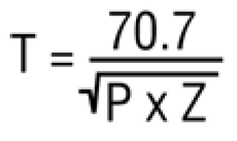
Where
T = turns ratio
70.7 = voltage of constant-voltage line
P = amplifier power output in watts
Z = amplifier rated impedance
SQR means square root
Better yet, measure the amplifier's output voltage at full power into its rated load impedance, and use the formula:
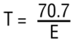
Where
T = turns ratio
70.7 = voltage of constant-voltage line
E = measured output voltage at full power into the rated impedance.
Amplifier with built-in transformer
If the transformer is already built into the power amplifier, simply look for the output terminal labeled "70V", "25V", “100V" or “high impedance".
Amplifier with transformerless, high-voltage output
Figure 2 shows how a power amplifier with a high output voltage can power a distributed system without a step-up transformer.
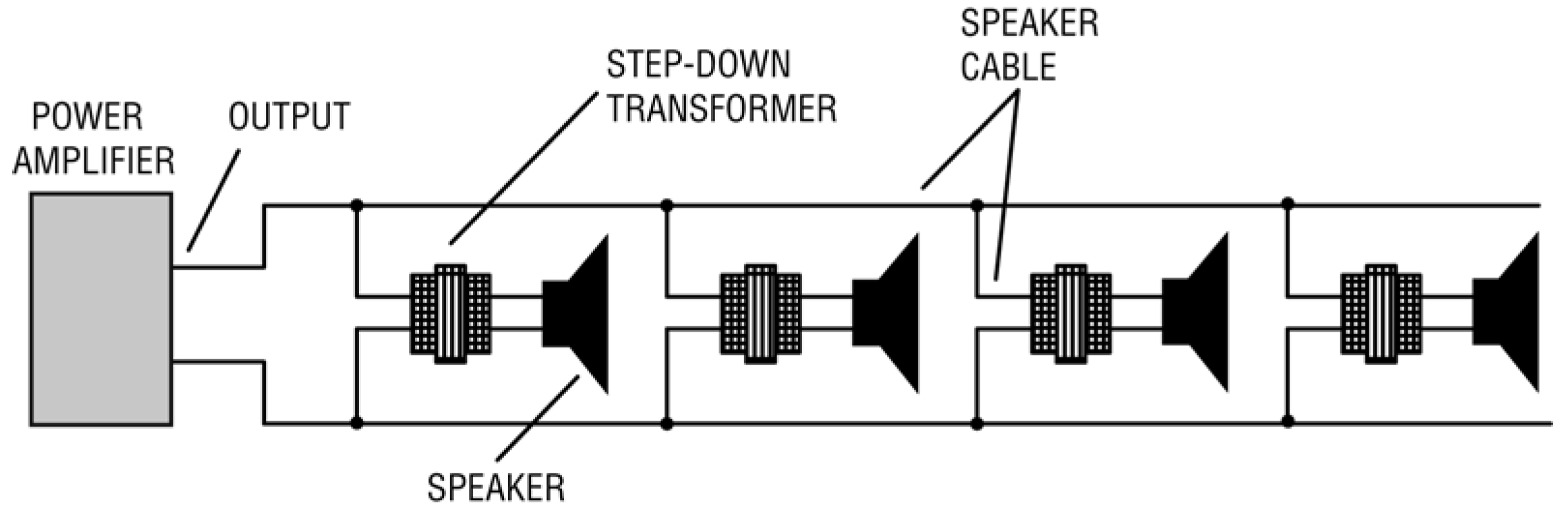
Figure 2. A constant-voltage system using a high-voltage power amplifier.
Many high-power amplifiers can drive 70V lines directly without an output transformer. Crown CH amplifiers have an auto transformer (except CH 4). CTs amplifiers can provide direct constant-voltage (70V/100V/140V/200V) or low-impedance (2/4/8 ohm) operation. In Dual Mode, the CTs 600/1200 can power 25/50/70V lines; the CTs 2000/3000 can power 25/50/70/100V lines. In Bridge-Mono mode, the CTs 600/1200 can power 140V lines; the CTs 2000/3000 can power 140V and 200V lines.
With CTs series amps, one channel can drive low-impedance loudspeakers, while another channel drives loudspeakers with 70V transformers. This makes it easy to set up a system with large, low-Z speakers for local coverage and distributed 70V speakers for distant rooms - all with a single amplifier.
The Crown CTs 2000 is unusually adept at providing constant power levels into various loads. In dual mode, it delivers 1000 watts into 2/4/8 ohms and into a 70V line. In bridge-mono mono, it delivers 2000 watts into 4/8/16 ohms, 2000 watts into a 140V line, and 2000 watts into a 200V line.
Pros and Cons of transformer-less systems
The high-voltage, transformer-less approach eliminates the drawbacks of amplifier transformers:
• cost
• weight
• limited bandwidth
• distortion
• core saturation at low frequencies.
On the other hand, transformers are useful to prevent ground loops, ultrasonic oscillations and RFI. Some local ordinances require transformer-isolated systems.
Let's look at the core-saturation problem in more detail. Sound systems can generate unwanted low frequencies, due to, say, a dropped microphone or a phantom-powered mic pulled out of its connector. Low frequencies at high power tend to saturate the core of a transformer. The less the amount of iron in the transformer, the more likely it is to saturate.
Saturation reduces the impedance of the transformer, which in turn may cause the amplifier to go into current limiting. When this occurs, negative voltage spikes are generated in the transformer that travel back to the amplifier - a phenomenon called flyback. The spikes cause a raspy, distorted sound. In addition, the extreme low-impedance load might cause the power amplifier to fail.
Some Crown amplifiers are designed with high-current capability to tolerate these low-frequency stresses. Production amplifiers are given a "torture test". Each amplifier must deliver a 15-Hz signal at full power into a saturated power transformer for 1 second without developing a hernia!
Many transformers are reactive, so their impedance varies with frequency. Some 8-ohm transformers measure as low as 1 ohm at low frequencies. That's another reason for specifying an amplifier with high current capability.
Conclusion
Using a high-voltage system greatly simplifies the installation of multiple-speaker P.A. systems. It also minimizes power loss in the speaker cables.
If you take care that your load does not exceed the power and impedance limits of your power amplifier, you'll be rewarded with a safe, efficient system.
