Room Buttons and Auto Panels in the Venue View
Example System
Associating Amp Channels to Rooms
Automatically created Room Buttons and Meters
Devices icon and Auto Panel buttons
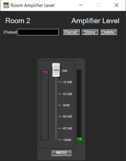
Room Amplifier Level
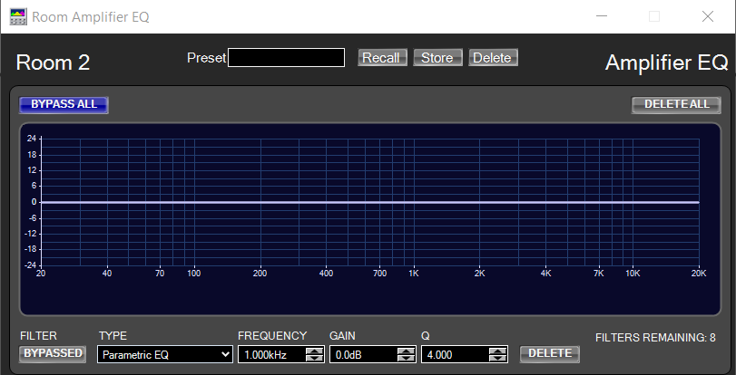
Room Amplifier EQ
Room Amplifier Level/Monitor
Room Amplifier Meters
Amplifier Error Monitoring
Error State hierarchy and colors
Error Monitoring Example
State Indication Settings
Error State 1 – All amps online
Error State 2 – an amplifier is offline
Error State 3 – amplifier warning
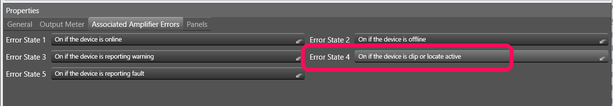
Error State 4 – amplifier clipping
Error State 5 – amplifier fault
Locate Active example
State Indication Settings and Error State setup
Locate Active results
Updating the Devices menu and Auto Panel menu for each room
Auto Panels
Master Panels and Monitor Panels
Custom Panels
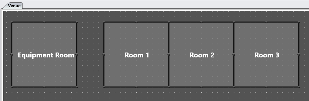
The Venue View in Audio Architect shows the Rooms in your Audio Architect system. For simplicity, we're assuming a single floor system.
Audio Architect automatically creates Auto Panels, Auto Panel buttons and Output Meters when amplifier channels are associated with rooms. Devices icon buttons are created on rooms that contain the actual equipment.
We'll start a simple three room system, with an equipment room.
We recommend a single room for equipment as this makes finding individual pieces easier, especially in larger systems.
There can be a rack for each room in this equipment room.
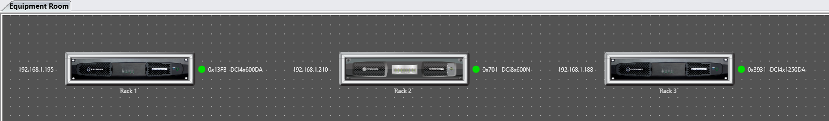
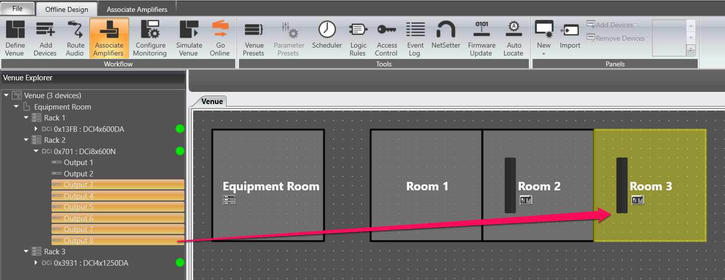
Once the amps are in their racks, associate them with the rooms in the Associate Amplifiers workflow.
You can drag a whole amplifier, or individual amplifier channels, from the Venue Explorer on the left to the rooms in the Venue.
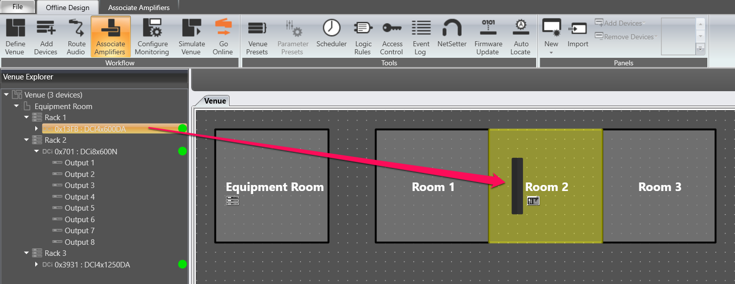
Hold down the Shift key to select multiple channels to drag over. Hold the mouse button on the last selected channel to maintain the selection while you drag them.
If you find you've made a mistake, you can clear the room association completely in the Associate Amplifiers tab.
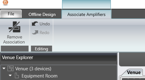
The Associated Channels pane below the Venue will let you remove channels individually.

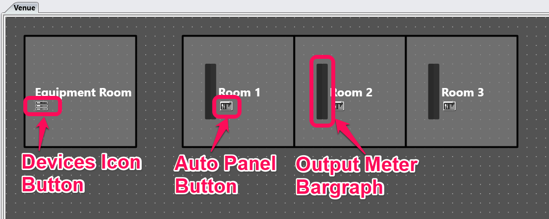
Assigning one or more amp channels to a room automatically adds a combined Output Meter and Auto Panel button access to the automatically created control panels.
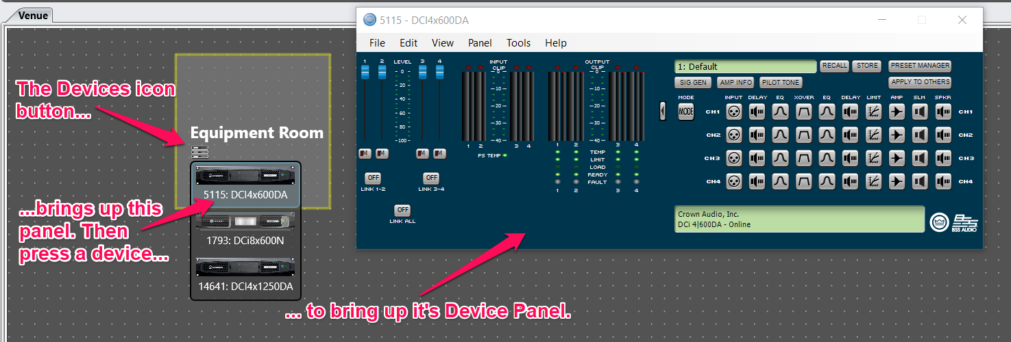
The Devices icon button automatically appears on rooms that contain equipment. It provides quick access to the Device Panel for each device, that is, the main control panel for each Crown amplifier.
The Room Output Meters and Auto Panel buttons will appear once amplifier channels are associated with a room.

This panel controls the level of the amplifier(s) associated to that Room. A Mute button is available to mute the amplifier(s), and Presets may be created, stored and/or deleted.
This is a Master EQ for the Room. If different channels associated to this room require separate equalization, do not use this function.
This panel provides the means to monitor and adjust the main functions of the amplifier(s).
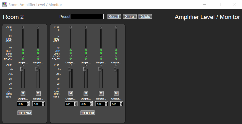
This panel allows you to view the metering of each amplifier.

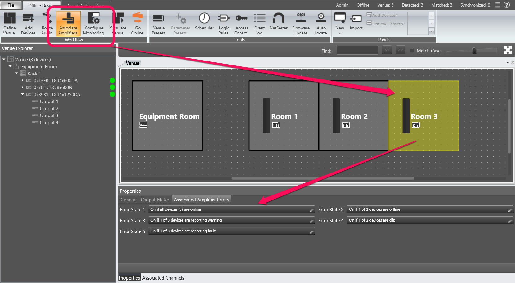
Once a Room has an amp channel associated, the Room can used to monitor amplifier status. This is set via 5 error states that are configurable via the Properties window for each room when you are in the Offline Design tab/Workflow/Associate Amplifiers or Offline Design tab/Workflow/Configure Monitoring.
The Error States are hierarchical, only one will show on a room at one time. Error State 5 has the highest priority and Error state 1 has the lowest priority in Audio Architect v2.25.1.4.
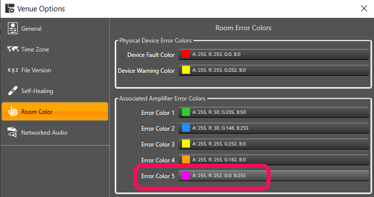
For this reason, we recommend setting the Error State colors to the reverse of their default settings.
Do this under File tab/Venue Options/Room Color. The reverse default color scheme is shown below.
Error Color 1: Lime Green
Error Color 2: Dodger Blue
Error Color 3: Yellow
Error Color 4: Orange
Error Color 5: Red

To setup the Error States, select the Associate Amplifiers or Configure Monitoring workflow, then select a Room.
Choose Associated Amplifier Errors in the Property window below the Venue view. The screenshot below shows the error states we have setup for Room 2.
Selecting one of the Error State dropdowns will bring up the State Indication Settings window.
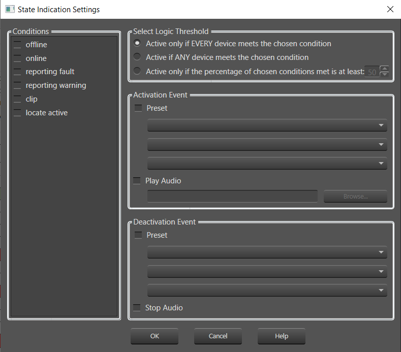
Conditions:
As indicated in the list, selecting one or more of these conditions sets the parameters for an Activation Event to take place.
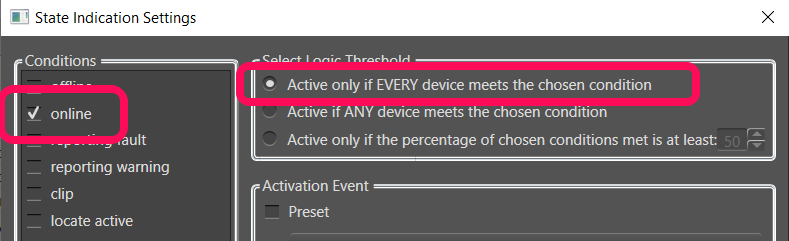
Select Logic Threshold:
The choice here will determine the how many devices are required to meet the chosen condition.
Activation Event:
Select Preset if you wish Audio Architect to activate a preset (such as a Level change) if the condition is met.
Select Play Audio if you wish an audio file to be played when the condition is met.
Deactivation Event:
When the condition is no longer met, you may activate a Preset as indicated above, or have the Audio file you may have selected to stop playing.
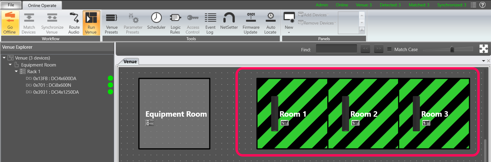
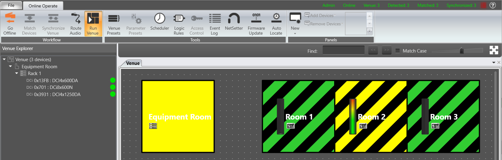
The lowest priority state – it shows only if there are no other error states present for the room amps.
This one shows Green if all the amps are online.
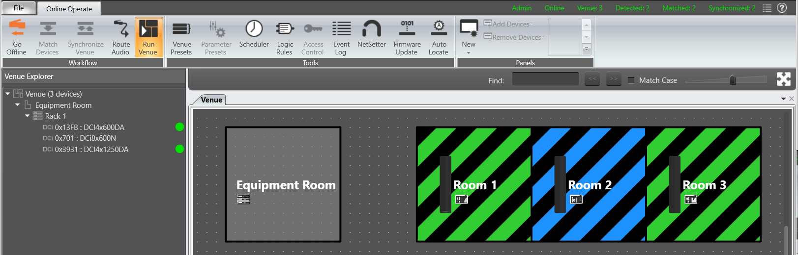
We have set this one to show the Blue state when any of the amps are offline.
This one shows the Yellow state when any of the amps have a Warning active.
Notice the Venue Physical Device Warning color also shows on the Equipment Room where the device is located.
This one shows the Orange state when any of the amps associated with the room have a channel in Clipping.
Clipping also triggers the Venue Physical Device Warning color that shows on the Equipment Room where the device is located.
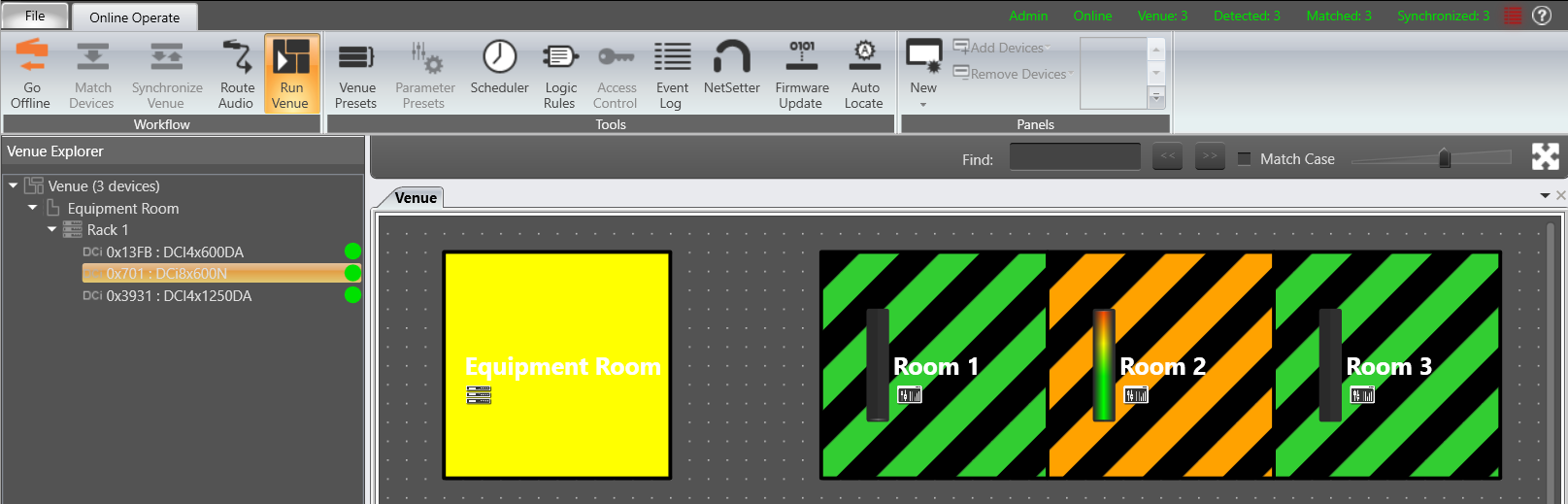
In this case, only one channel is in clipping, in Room 1. But because the amplifier also has channels associated with Room 2, both show the Error 4 Orange state.
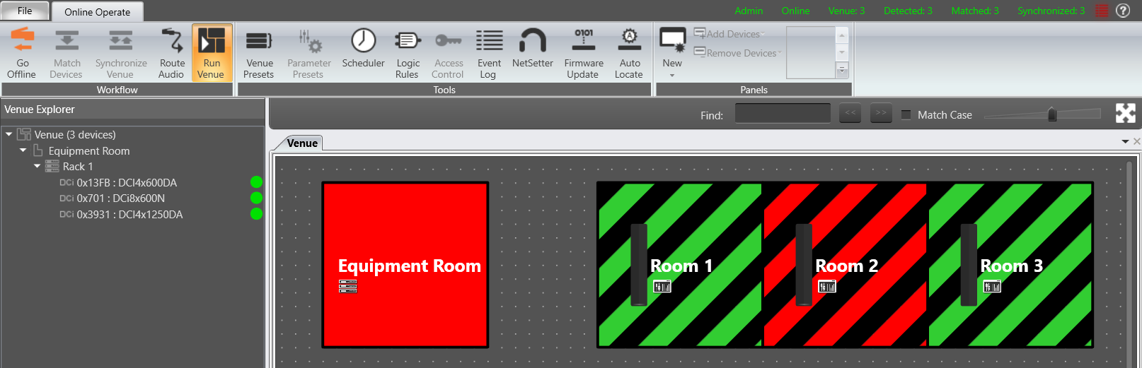
This one is setup to show the Red state when any of the amps have an Amplifier Fault active, generally anything that will shut down an output. In this case, an output short on an amplifier only associated with Room 2.
Error State 5 is now showing on Room 2, taking priority over the Clipping Error state that is also present.
The Venue Physical Device Fault color now shows on the Equipment Room where the device is located, also taking priority over the device Warning color.
Locate Active is the other condition that can trigger an error state. This may be useful in a large system with lots of amplifiers, to visualize which rooms have an associated channel from that amp.
Here we set State 5 up for Locate Active on Any Device in all rooms, and setup a unique color for this test in Venue Options:

However if you want to make less changes, you could double up Locate Active on one of the states that is unlikely to be active during your test, for example Clip:
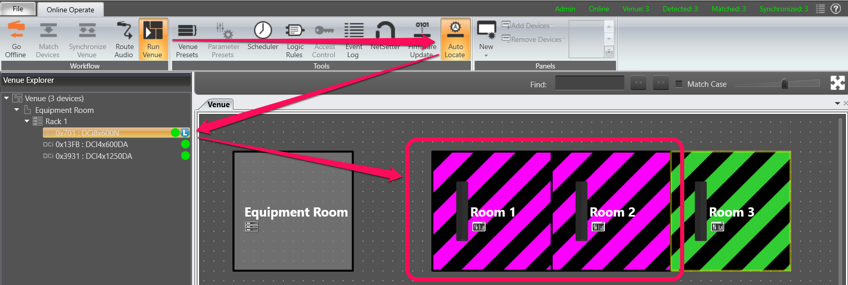
Locate Amp 1
The amplifier in the Room 1 rack has channels associated with both Room 1 and Room 2.
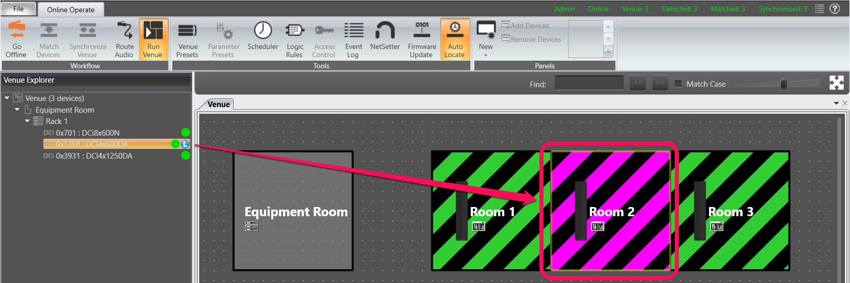
Locate Amp 2
The amplifier in the Room 2 rack has its channels associated with Room 2 only.
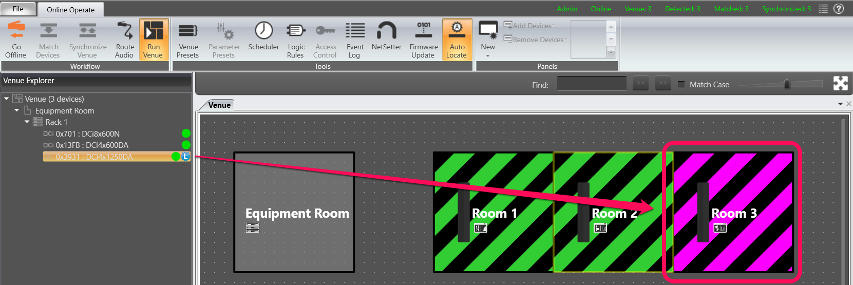
Locate Amp 3
The amplifier in the Room 3 rack has its channels associated with Room 3 only.
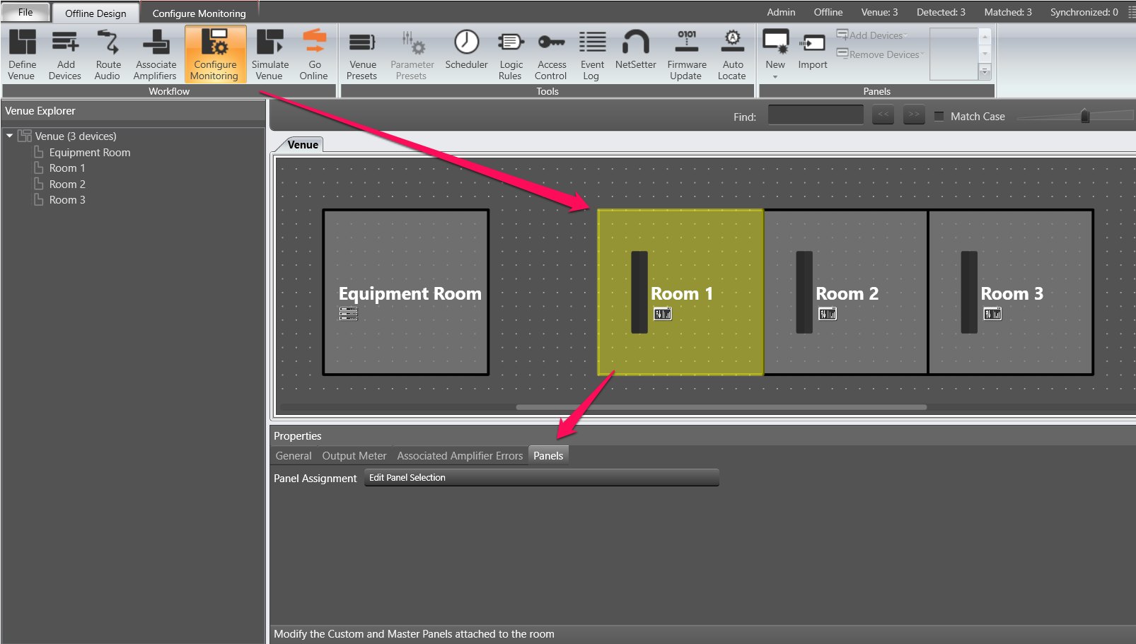
You can change which panels show when you press the Device button and Auto Panel button, under Offline Design/Workflow/Configure Monitoring.
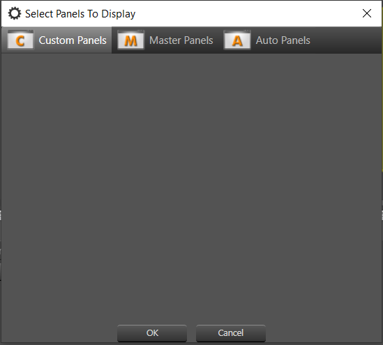
For example, to update the Room 1 Auto Panel selection, select Room 1 then choose the Panel tab in its Properties window and choose the Edit Panel Selection drop down:
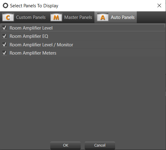
The Auto Panels are automatically checked. You may uncheck any you do not want to use.
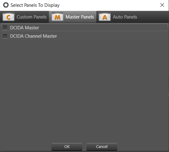
Any master or monitor panels created in the system may be selected here. They are not selected by default.
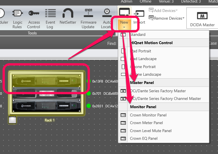
Master panels and Monitor panels are created by selecting one or more similar amplifiers in Offline Design, then choosing the dropdown arrow below New in the panels section of the ribbon. Options for these panels will show up in the New Panels menu.
Custom panels created in the system may also be selected here. They are not selected by default.
This example system does not contain any custom panels.