Adding More Inputs to the Compact Stagebox
The default configuration for the Compact Stagebox is 32x16. This can be modified to be 48x16.
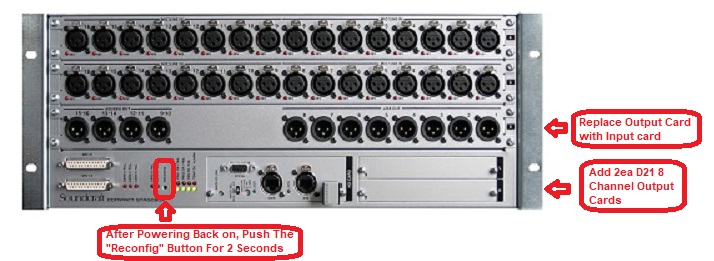
By adding an additional 16 channel input card in Slot E (removing the output card), then installing 2ea D21 expansion cards in Slots L and K, you will have 48 inputs and 16 analog outputs. The first step is to purchase the required cards.
The following parts are required:
1ea - 16 Mic Channels for CSB Soundcraft Part# A947.04300SP
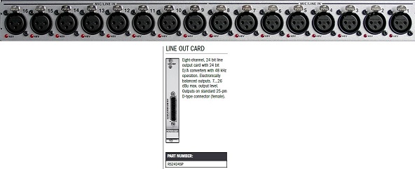
2ea - 8 Analog Line Out D21 Soundcraft Part# RS2424SP
Additionally, seeing the outputs are on DB25 connectors, you can purchase the following input panel and connecting cables, installing 16 channel male xlr panel under compact stagebox in a rack.
1ea - 16 XLR Male Panel Soundcraft Part# RS2546SP
2ea - DB25 3 Foot Cable Soundcraft Part# C089.201174
NOTE: On Si mixers, the MADI/USB expansion card, part# 5046678.v, will not allow more than 32 input channels so that card is not supported for the higher channel count. Make sure to use any other supported MADI card:
Single Mode Optical - 5019983.v
Multimode Optical - A520.001000SP
Dual Cat5 - A520.005000SP
Installing the Input and Output cards in the Compact Stagebox
In order to replace an input or output module [e.g. if more inputs or outputs are required], first switch the Compact Stagebox OFF and unplug the power cable(s).
- Observe the precautions for handling devices sensitive to electrostatic discharge.
- For all screws in question a no. 2.5 Allen screwdriver is used.
- Remove the top cover of the Compact Stagebox (2 countersunk screws M4x8 on top, 13 screws M4x6 around the upper edge).
- Then remove the module concerned. Unplug the flat cable from the backplane PCB and the supply loom from the module.
- Remove the 4 screws M4x6 at the modules edges.
- Insert the new module and fix it with the 4 screws. Connect the flat cable to the corresponding socket on the backplane PCB (for correct connection refer to the illustration below).
- Connect the supply loom to the module. Supply looms are identical for input and output modules, no particular order has to be followed when reconnecting them. Like the power connections in a PC, there is one connector more than modules to feed; the fourth connector is not used.
- For fixing the top cover it is recommended to tighten all screws only after all of them have been inserted a few tums into their threads.
Connect the Compact Stagebox back to power, switch it on and press the RECONFIG button with a small tool (e.g. the Allen screwdriver used before).
NOTE: The new input/output count needs to be configured in your console's I/O mapping. Please refer to its user guide.
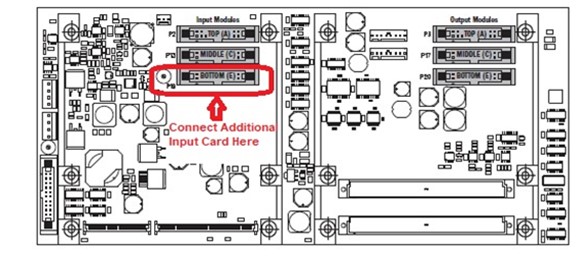
The 3 module slots are labeled A, C and E; they correspond to the connectors of the backplane PCB according to the illustration above. There are 3 connectors on the left for input modules, and 3 on the right for output modules. Modules must be connected to the correct connector in order to have a correct assignment of input and/or output channels.
In the standard configuration (2 input modules in slots A and C, and 1 output module in slot E), the modules are connected as follows.
- Input module A 4 top connector on the left side of the backplane (P2).
- Input module C 4 middle connector on the left side of the backplane (P13).
- Output module E 4 bottom connector on the right side of the backplane (P20).
To configure the Stagebox with 3 input modules to give a 48 input x 0 output Stagebox, they are connected as follows:
- Input module A 4 top connector on the left side of the backplane (P2).
- Input module C 4 middle connector on the left side of the backplane (P13).
- Added input module E 4 bottom connector on the left side of the backplane (P19).
Supply looms are identical for input and output modules. No particular order has to be followed when re-connecting them. Like the power connections in a PC, there is one connector more than modules to feed; this connector is not used.
INSTALLING D21m I/O CARDS
In the K and L slots, one or two additional D21m input or output cards may be installed. In order to do so, first switch the Compact Stagebox OFF and unplug the power cable(s).
- Remove the blank panel(s) with a size 2 screwdriver and insert the D21m card(s).
- Re-tighten their screws.
Connect the Compact Stagebox to power, switch it on and press the RECONFIG button with a small tool (e.g. a size 2.5 Allen screwdriver).
NOTE: The new input/output count needs to be configured in your console's I/O mapping. Please refer to its user guide.
For more information on the D21m cards please refer to:
Vi 1nput/0utput Option Cards Technical Information
