When designing a sound and control system using Soundweb London, it can become necessary to implement some form of priority to manage the routing of audio signals which should have precedence over others, to override preset events or to establish the behavior of controls and indicators on a Custom Control Panel. These implementations of priority are associated with applications such as paging, fire alarm muting, systems requiring sequenced timed events and advanced user interfaces. These applications are made possible, with any degree of complexity, because audio Processing Objects, Custom Control Panel Objects, Control Ports or Serial Ports can be integrated into the Logic Configuration.
Priority using the Truth Table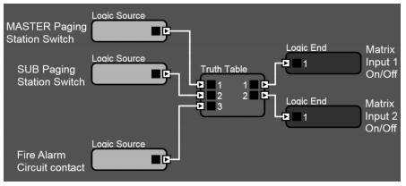
The Truth Table sets its outputs according to rules associated with its input states. These rules can be defined to provide priority in a combinational or sequential manner. The following combinational example shows the Truth Table being used in a single zone paging system comprising two paging stations integrated with a fire alarm trigger.
Each paging station button routes its microphone signal to the Analog Output by means of a Matrix Router. The fire alarm trigger must be able to prevent the microphone signals from reaching the Analogue Output to allow the external fire alarm announcement to be heard.
In this system, the Master paging station needs to have priority over the Subordinate paging station, therefore one must be able to override the other. The fire alarm trigger must have priority over both paging station A and B.
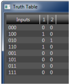
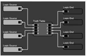
In the Logic configuration, the two paging buttons and fire alarm contact have been linked to three Logic Sources. The Matrix Router On/Off crosspoint parameters have been linked to Logic Ends. The Truth Table has been programmed to produce the appropriate output states taking into account all the possible input state combinations as shown below.
Using the Truth Table for priority is simple to set up and easy to adjust at a later date. However, it becomes cumbersome to implement with very large numbers of inputs and outputs. We shall encounter further examples using the Truth Table in the sections which follow.
�
Priority Logic Circuit – First come first served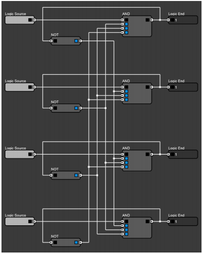
One of the most common forms of priority requires that when one input is activated it cannot be overridden by another until the first is deactivated. This behavior is usually required in paging systems to prevent an active page being interrupted.
The following example logic circuit achieves this behaviour on four inputs using Boolean Logic Objects. To demonstrate the functionality of the circuit, Logic Sources are used as inputs and Logic Ends as outputs. In a typical paging application the Logic Sources could be linked to a Control Input which is triggered by a momentary paging switch. The Logic Ends could be linked to an Audio Processing Object and/or linked to a Custom Control Panel Indicators.
Each Logic Source is connected to its corresponding AND object who’s function is to allow or disallow the logic from propagating to the Logic End. The output of each AND object is also connected to a NOT object then onwards to the inputs of all the other AND objects.
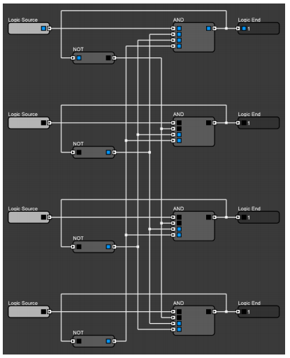
The AND objects are now interconnected and will operate in the following manner:
- When none of the Logic Sources are active, all but one of the inputs of the AND objects are held high, thanks to the NOT objects who’s state is driven by the output of the AND objects.
- If a Logic Source is held high (triggered by the Paging switch) then the output of the corresponding AND object will go high, since the output of the AND object will only go high when all its inputs are high.
- If a second Logic Source is held high then the output of the corresponding AND object will not go high therefore this state will not pass to its corresponding Logic End.
Once the first Logic Source returns to a low state, the second Logic Source’s logic will be allowed to propagate to the Logic Source.
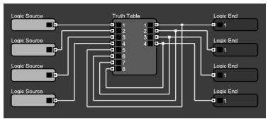
It is possible to accomplish this functionality with a Truth Table. The sequential behavior is achieved by wiring the outputs to a set of additional inputs. Modifying or expanding this Truth Table to provide for additional Logic Sources or Logic Ends makes programming more difficult because there are 256 input combinations.
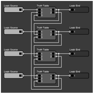
Using several identical Truth Tables provides a more manageable way to expand or modify such a logic circuit. In the example below, the Truth Table objects are programmed with the same rules and easily wired together in a specific fashion. Output 2 is wired to input 2 of the next object. The last object is then wired up to the first object.
Priority Logic Circuit – Highest wins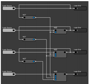
Another common type of priority requires that when two or more inputs are activated then only the output with the highest priority is activated. This provides a way to implement a hierarchical mechanism with a system consisting of several paging stations.
As in the last example, this behavior is achieved using Boolean Logic Objects. All Logic Sources are connected to a corresponding AND object except the one with the highest priority. This Logic Source is connected directly to its output Logic End while still interconnected with the AND objects.
The same functionality can also be achieved using a Truth Table with four inputs and four outputs. This provides simple combinational logic and is easy to program and modify since there are only 16 inputs combinations.
�
 Priority Logic Circuit – One master
When used in combination, the logic circuits above can provide further useful mechanisms. One example of these requires that when one input is activated it cannot be overridden by another until the first is deactivated but it can be overridden by a specific input.
This behavior gives equal priority to all inputs except one which can always take precedence at any time. As a paging system this would manifest as a number of “first come first served” paging stations with an additional “master” paging station which might be used for emergency announcements.
All Logic Source are connected to a corresponding AND object except the one intended to override the others. This Logic Source is connected directly to its output Logic End while still interconnected with the AND objects.
Priority Logic Circuit - More zones
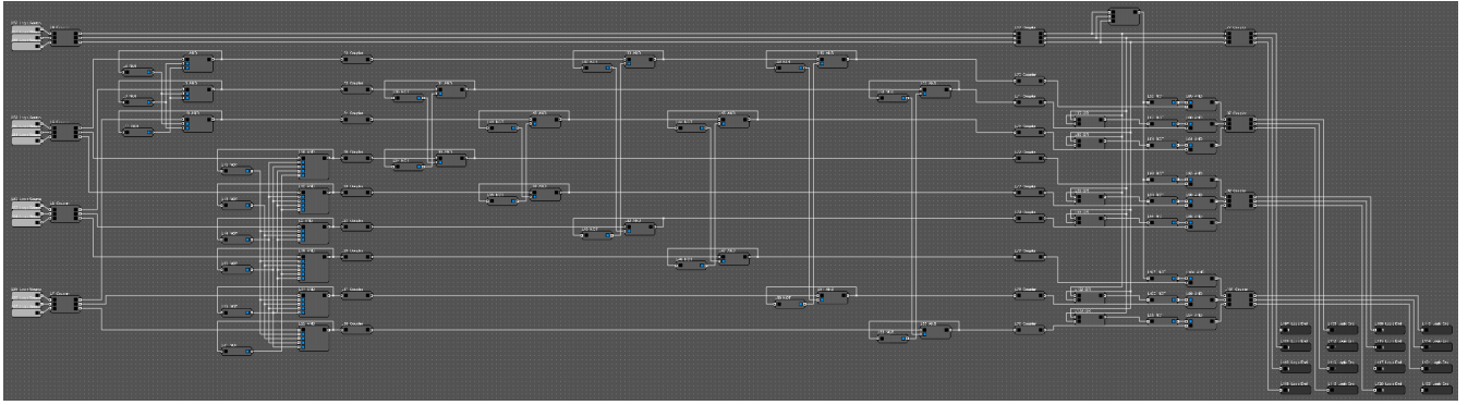
In practice, the above examples would provide the necessary Logic for multiple paging stations to page a single zone. If there were multiple paging stations and multiple zones, then we need to duplicate the chosen logic circuit for each zone and combine them together. The order of the combined logic circuit is important because it determines the eventual functionality. As a general rule, the last circuit in the chain takes precedence.
The circuit below provides priority logic for four paging stations that can page the other three. Each can page a zone unless another paging station is already paging it. The master paging station has priority over the others so that it can interrupt a page from another paging station. The Logic Ends on the right are linked to a Matric Router that routes the audio from the paging mics to the zones.